6
I
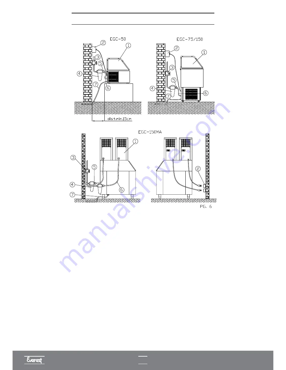
TYPICAL INSTALLATION DIAGRAM
1) Ice cube machine.
2) Female electrical outlet.
3) Water supply valve.
4) Water filter.
5) Hydraulic connection filter / water inlet hose.
6) Flexible water inlet hose.
7) Flexible water outlet hose (for sewage entry point).
Notes:
1 • Diagram for installer's guidance only.
2 • Items 2 and 3 of the installation diagram are not an integral part of the equipment.
3 • The buyer is responsible for installing the equipment.
4 • For the EGC-50A machines, provide a minimum space of 15cm at the sides, rear and top part for
ventilation.
5 • For the EGC-75A, EGC-100A, EGC-150A and EGC-150MA machines, provide a minimum space of
20cm on the sides and rear for ventilation.
Summary of Contents for EGC 100 A / 150 A
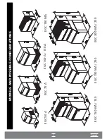
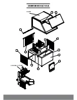
Page 12: ...OVERVIEW EGC 50A COVER COOLING SYSTEM...
Page 14: ...13 I OVERVIEW EGC 150MA I...
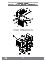
Page 15: ...14 COOLING SYSTEM EGC 50A EGC 75A EGC 100A AND EGC 150A I COOLING SYSTEM EGC 150MA I...
Page 16: ...ELECTRICAL ELECTRONIC PART...
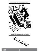
Page 17: ...TROUGH DISPLACEMENT SYSTEM DISPLACEMENT ARM ASSEMBLY TROUGH...
Page 36: ...35...

