background image

Summary of Contents for Everdisk

Page 1: ...VERE Everdisk rM internal external hard disk subsystem XT compatible OWNER S MANUAL AND REFERENCE GUIDE VERSION 2 0 EVER for EXcellence MAN 00007 20...

Page 2: ......

Page 3: ...Everdisk internal external hard disk subsystem XT compatible OWNER S MANUAL AND REFERENCE GUIDE EV 390 EV 391 EV 392 VERSION 2 0 EVEREX SYSTEMS INC 48431 MILMONT DRIVE FREMONT CA 94538...

Page 4: ...Everex Systems will not be responsible for loss of data resulting from the use of this product This manual is copyrighted All rights are reserved This manual may not in whole or in part be copied phot...

Page 5: ...of Microsoft Corporation Compaq and Deskpro are trademarks of Compaq Computer Corporation Micropolis 1333A and 1335 are trademarks of Micropolis Corporation Miniscribe 3650 is a trademark of Miniscri...

Page 6: ...d wircs are tightly secured 2 Reorient the computer with respect to the receiver 3 Move the computer away from the receiver 4 Plug the computer into a different outlet so that computer and receiver ar...

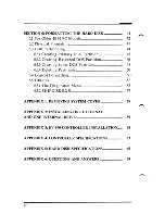
Page 7: ...RIVE CONFIGURATION 10 3 1 Drive Select Switch _ 10 1 3 2 Terminating Resistor _ _ 16 SECTION 4 CONTROLLER CONFIGURATION 19 4 1 Controller Description __ _ _ 20 4 2 Controller Configuration _ 21 SECTIO...

Page 8: ...ting Super DOS Partition _ 48 6 3 4 Deleting Partitions 50 6 4 Logical Formatting _ 50 6 5 Utilities _ 53 6 5 1 The Diagnostics Menu _ _ _ 53 6 5 2 SHIPDISK EXE _ 57 APPENDIX 1 REMOVING SYSTEM COVER m...

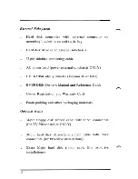
Page 9: ...tic bag Hard disk drive in an anti static bag 34 pin ribbon cable 20 pin ribbon cable Half height bezel full height bezel optional Metal mounting brackets Set of screws EVERDISK utility diskette Versi...

Page 10: ...EVERDISK utility diskette Version 3 0 or later EVERDISK Owner s Manual and Reference Guide Owner Registration and Warranty Card Foam padding and other packaging materials Optional Items 34 pin floppy...

Page 11: ...ISK subsystem if you ever need to return your EVERDISK subsystem to Everex Systems for any reason without proper packaging your warranty may be affected As with any major purchase please save your sal...

Page 12: ...damaged by static electricity to avoid such damage touch the system chassis before handling the drive and controller and try not to touch the circuitry on the drive and controller Also limit your mov...

Page 13: ...rex dealer REMEMBER If all else fails read the instructions Introducing the EVERDISK Subsystem The EVERDISK hard disk subsystem offers superior performance reliability and rugged construction in hard...

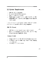
Page 14: ...ut Please refer to the appropriate section below for special requirements if you have the following computers IBM PC Portable IBM Portable front bezel for hard disk optional Special short mounting scr...

Page 15: ...DOS 2 11 or IBM PC DOS Version 2 1 or later Compaq Deskpro mounting rails Deskpro power cable Y power cable optional Other PC Compatibles MS DOS Version 2 1 or later older MS DOS versions will not wo...

Page 16: ...the drive s terminating resistor 2 Configure the SWl jumper block for the type of drive you will connect to the controller 3 Attach the 20 pin and 34 pin ribbon cables to the controller 4 Install the...

Page 17: ...power supply to the controller 4 Connect the 37 pin cable to the 37 pin connectors on the controller board s mounting bracket and the external hard disk subchassis 5 If applicable connect the AC powe...

Page 18: ...Make sure your drive s terminating resistor is selected properly 3 1 The Drive Select Switch Before you install the hard disk drive make sure the drive select switch is configured properly The drive...

Page 19: ...the cable connectors Put a jumper on DS1 Drive Select 1 if the drive is the first drive in your system or DS2 if the drive is the second drive in your system Refer to the following figure Please note...

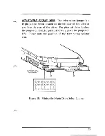
Page 20: ...8 pin jumper J9 refer to Figure 1B For physical drive 1 put the jumper on DS1 for physical drive 2 put the jumper on DS2 Please note the location of the terminating resistor also RESISTOR TERMINATION...

Page 21: ...ter select drive address 2 if the 5146 is the second drive in your computer Refer to the following figure In this figure note the location of the SWI terminating resistor dipswitch POWER SUPPLY SW1 SW...

Page 22: ...positions For physical drive 1 put jumper on position DSl for physical drive 2 put jumper on position DS2 Please note the position of the terminating resistor also o J2 D PIN 1 o COMPONENT SIDE J1 o...

Page 23: ...drive as you face the rear of the drive For physical drive 1 place the jumper on DSO for physical drive 2 place the jumper on DSl Please note the position of the terminating resistor also TERMINATING...

Page 24: ...sistor installed If the controller has two drives connected to it the drive attached to the middle of the daisy chain cable must have its terminating resistor removed Removing the Terminating Resistor...

Page 25: ...RIVE SELECTION 1 TERMINATOR INSTALLED Figure 2A One Drive Configuration I CONTROLLER I I L TERMINATED DRIVE 1 DRIVE 2 DRIVE SELECTION 1 DRIVE SELECTION 2 TERMINATOR REMOVED TERMINATOR INSTALLED Figure...

Page 26: ...the only drive connected to daisy chain cable Switch positions 2 to 8 ON position 1 should be OFF I I 0 CONTROLLER N t 12345678 Example 2 5146 is connected to middle of daisy chain cable Switch posit...

Page 27: ...ch as the capacity in megabytes and how many heads and cylinders the drives have You need to place the jumper shunt on the pins at SWI according to the type of drive s you are installing WARNING Circu...

Page 28: ...EVERDISK subsystems are delivered with the EV 392 controller board The EV 392 is similar in size to the EV 391 controller but the EV 392 uses RLL 2 7 encoding which records 26 sectors per track on a h...

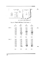
Page 29: ...and 3 97 that support specific drive types Table 1A ROM BIOS Disk Type Selection EV390 391 shows the proper configuration of SW1 see Figures 3 and 4 for SW1 configuration options and the type of EPRO...

Page 30: ...igure 3 The EV 391 Hard Disk Controller A B C D Option Option Option Option Drive 1 5 5 5 5 1 6 6 6 6 7 7 7 7 8 8 8 8 4 4 4 4 3 3 3 3 2 2 2 2 1 1 1 1 SWl SWl SWl SWl 5 5 6 6 6 6 7 7 7 7 8 8 8 8 4 4 4...

Page 31: ...Figure 4 The EV 390 Hard Disk Floppy Disk Controller A B C D Option Option Option Option Drive 1 5 5 5 5 6 6 6 6 7 7 7 7 8 8 8 8 4 4 4l 4 3 3l 3 3l 2 2 2 2 1 1 1 1 SWI SWI SWI SWI Drive 2 5 5 5 5 6 6...

Page 32: ...J2 J1 L ___ r l W8 W4 l 1 I W3 J4 J4 37 PIN FEMALE BRACKET CONNECTOR Figure 5 The EV 392 Hard Disk Controller Option Drive 1 A 56781234 B J 5 678 234 c fil I I 5678 234 D 5678 234 Drive 2 1 11 1 1 Jl...

Page 33: ...S NS NS NS A NEe 5146 42 8 615 NS NS B B NS NS Seagate ST213 10 7 2 615 B B NS NS NS B Seagate ST225 21 4 4 615 e e e e e e Seagate ST251 42 8 6 820 NS NS D D NS NS Seagate ST4026 21 4 4 615 e e e e e...

Page 34: ...65 981 5 A Vertex V150 65 981 5 A Priam V170 92 987 7 B Miniscribc 3425 31 612 4 C Microscicncc HH725 31 612 4 C Seagate ST238 32 615 4 D NOTE The drives listed in Table 1B are all qualified for RLL...

Page 35: ...der upgrading the power supply for the hard disk subsystem to work properly 5 1 Installing the Controller 1 Remove the hard disk drive controller board cables mounting hardware and the EVERDISK softwa...

Page 36: ...r the drive you have see Section 4 2 for instructions on configuring the controller 5 Locate an available expansion slot cover nearest the floppy disk controller and remove the screw that holds the ex...

Page 37: ...ripe on the cables to the silkscreened 1 on the controller COMPONENT SIDE Figure 7 Attaching the Cables to the Controller 7 Insert the controller into the available expansion slot making sure the gold...

Page 38: ...OFF the system and remove all power cables from the system Clear an area around your computer to leave plenty of room to work 3 Install the controller according to the instructions 10 Section 5 1 4 M...

Page 39: ...lly into the drive space with the metal cover face up Connect the cables from the controller to the drive according to Figure 10 The colored stripe on the cables should be on the left side as you face...

Page 40: ...ge the switch settings on your system motherboard unless you removed the floppy disk drive and replaced it with the hard disk drive in this case refer to your system s manual on how to reset your moth...

Page 41: ...12 When the drive is formatted and working properly turn OFF the system and reinstall the system cover 33...

Page 42: ...switch and terminating resistor on each internal drive are adjusted according to instructions in Section 3 1 and 3 2 3 Connect the 20 pin data cable from drive 1 to the 12 connector and the 20 pin dat...

Page 43: ...nects to drive 2 Make sure the colored stripe on the cables connect is on the left side as you face the front of the system The end connector of the daisy chain cable should be connected to drive 2 th...

Page 44: ...install all cables and turn the computer ON 8 Follow the instructions in Section 6 to format the two hard disk drives Note that your second drive is normally addressed as the D drive 9 When the drives...

Page 45: ...oard in Section 5 1 2 Plug one end of the shielded round cable to the external connector on the controller and the other end to the external connector on the hard disk subchassis Figure 12 Connecting...

Page 46: ...Turn the chassis ON first then turn the computer ON with the DOS system diskette in drive A 5 Format the drive by following the instructions III Section 6 of this manual 6 Once the drive is formatted...

Page 47: ...subchassis plug in a 4 wire power cable from the power supply to the J5 connector on the controller board if there are no spare power cables available disconnect a 4 wire cable from your currently ins...

Page 48: ...ve subchassis make sure you configure the hard disk controller board so two drives are usable by the controller see Section 4 Then use the instructions in Section 5 3 1 to connect your two drive subch...

Page 49: ...data to and from that partition Everex Systems has included with your EVERDISK hard disk subsystem the EVERDISK utility diskette Version 3 0 or later which contains programs that will perform the thre...

Page 50: ...ard disk subsystem On the left hand side of your IBM PC motherboard near the speaker is a white label which indicates the model number of the Pc If it is labeled 16K 64K CPU you have a PC 1 if it is l...

Page 51: ...Main Menu press the F2 key Physical Format to begin the physical formatting process 3 You will see the following menu fields Enter physical disk number Enter number of cylinders in disk Enter number o...

Page 52: ...d type 400 Enter 2 Enter If you want to insert any bad tracks press the F5 key if you want to delete any bad tracks press the F6 key after placing the cursor on the bad track entry you want deleted 5...

Page 53: ...cylinder of partition ddd Where aaa represents the largest free space on the drive bbb represents the maximum size of a partition If the drive is less than 32 megabytes in capacity bbb will equal the...

Page 54: ...O key to return to the DISK Main Menu NOTE You must activate your Primary DOS partition for the drive to be bootable from DOS If your drive has a capacity greater than 32 megabytes you have two option...

Page 55: ...tition fields Enter the values you want and press the FS key to create the partition 4 The Partition Menu window will then be replaced by a new Create Logical DOS Drive window with the following field...

Page 56: ...ompted to continue creating Logical drives until you have no more space to create a Logical drive in the Extended DOS partition 7 You will notice in the Partitions menu two new partition types Ext DOS...

Page 57: ...ar to the one for creating a Primary DOS partition see Section 6 3 1 except this time the maximum number of cylinders allowed in a partition bbb will equal the maximum number of available cylinders aa...

Page 58: ...e partitions you want deleted and press the F2 key again to confirm your selection WARNING If you delete the Primary DOS Partition the hard disk drive will not be bootable from DOS 3 Press the F8 key...

Page 59: ...iles otherwise enter N If you want a volume label for your drive enter a volume label name up to 11 characters long 3 Press the FS key to begin the logical format This process takes a few minutes to c...

Page 60: ...ve door is open then proceed to reboot the system When your system comes up with a C prompt your hard disk is ready for use 8 If your disk contains more than one DOS usable partition eg Extended DOS o...

Page 61: ...OS 6 5 Utilities 6 5 1 The Diagnostics Menu The EVERDISK utility diskette also includes a senes of diagnostic tests intended to ensure that your hard disk and hard disk controller are working properly...

Page 62: ...ht group select the physical drive you want to test select whether or not to do a continuous test and select the duty cycle NOTE For the duty cycle we do not recommend entering 100 percent if you choo...

Page 63: ...drive Checks to make sure the drive can read data from disk in sequential order from cylinder 0 head 0 to end of drive Checks to make sure the drive can write and read in sequential order from cylind...

Page 64: ...s Runs all the tests listed above WARNING The Sequential Write Sequential Write Read Random Write Random Write Read and All Tests diagnostics selections will destroy data already on the disk For these...

Page 65: ...skette in drive A 2 Type 1 SHIPDISK Enter 3 The program will ask you for a drive number 1 8 Enter 1 for physical drive 1 enter 2 for physical drive 2 If two drives are connected to your system you mus...

Page 66: ...cover First remove the holding screws from the edges of the back panel of the system unit save the screws With the front of the unit facing you carefully pull the cover towards you until it stops Til...

Page 67: ...al drive 3 Change the 20 pin data cable from 12 to 13 the external drive is connected to the controller via the J4 bracket connector 4 Format the external drive as drive C and the internal drive as dr...

Page 68: ...WARNING DO NOT remove the cover of the external hard disk drive subchassis some of the components inside can produce electrical shock 60...

Page 69: ...ge required for this controller is the installation of a floppy disk ribbon cable To install the hard disklfloppy disk controller 1 Remove the floppy disk controller card already in your system 2 Atta...

Page 70: ...lor stripe on the cable should be on the right side as you see the component side of the controller See Figure 16 3 Connect the cable s middle connector to drive B and connect the end connector to dri...

Page 71: ...Cylinders Per Drive Up to 1024 Bytes Per Sector 512 Sectors Per Track 17 EV 390 391 26 EV 392 Head Selects 16 Drive Selects 2 Data Transfer Rate 5 Mbits sec EV 390 391 7 5 MBits sec EV 392 Write Preco...

Page 72: ...Voltage 5VDC 5 and 12VDC 10 Maximum Current depends of drive type Environmental Limits Ambient Temperature 0 550 C 32 1310 Fahrenheit Relative Humidity 10 95 non condensing Altitude 0 3000 meters 0 98...

Page 73: ...Tracks Encoding Type Transfer Rate Mbits second Average Access msec TABLE 3 Hard Disk Specifications I Seagate Seagate Seagate Seagate ST225 ST251 ST4026 ST4038 21 4MB 42 8MB 21 4MB 31 9MB 4 6 4 5 615...

Page 74: ...eagate ST4096 NEC 5146 Miniscribe 3650 Formatted Capacity 42 5MB 80 2MB 42MB 42 2MB Heads 5 9 8 6 Cylinders 977 1024 615 809 Tracks 4885 9216 4920 4854 Encoding Type MFM MFM MFM MFM Transfer Rate Mbit...

Page 75: ...rmatted Capacity Heads Cylinders Tracks Encoding Type Transfer Rate Mbits second Average Access msec Micropolis 1333A 44 5MB 5 1024 5120 MFM 5 30 Micropolis 1335 71 3MB 8 1024 8192 MFM 5 30 Seagate ST...

Page 76: ...ive installed Q When I boot up the message 1701 hard disk not recognized comes up What should I do A The most likely problem is that your hard disk subsystem is not securely installed in your computer...

Page 77: ...should I do A Make sure you followed the formatting instructions in Section 6 properly we suggest doing the entire formatting process again If you still have a lot of bad tracks try removing some of y...

Page 78: ...k drive with one type of controller and then replaced the controller with another type you must reformat the drive for the newer controller to work with your drive Please refer to Section 6 of this ma...

Page 79: ...71...

Page 80: ...EVEREX SYSTEMS INC 48431 MRMONT DRIVE FREMONT CA 94538 SALES 415 683 2100 TECH SUPPORT 415 498 1115 FAX 415 651 0728 TELEX 5101000590 MAN 00007 20...

Reviews: