background image

- 8 -

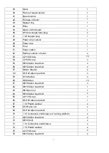
77 

Ф6 washer 

78 

M6 Nylon nut 

79 

M8*65 Allen head bolt 

80 

Support cushion of running deck 

81 

4.2*15 Screw 

82 

Side rail cushion 

83 

M8*85 Allen head bolt 

84 

M8*50 Allen head bolt 

85 

5 washer 

86 

M5*10 bolt 

87 

2.9*6 Screw 

88 

M8*20 Allen head bolt 

89 

Ф8 Spring washer 

90 

M8*12 bolt 

91 

M8*60 Allen head bolt 

92 

4.2*12 Screw 

93 

Computer display board 

94 

Overlay 

95 

Control wire of computer 

96 

Control wire of upright 

97 

Control wire of base frame 

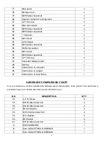
HARDWARE COMPARISON CHART 

For your convenience, we have identified the hardware used in the assembly of this product. The chart below is 

provided to help you to identify items that may be unfamiliar to you.   

NO. 

DESCRIPTION 

Q'TY 

53 

4.2*15 Screw 

55 

M8*20 Allen head bolt 

56 

M8*30 Allen head bolt 

57 

Ф8 Arc Washer 

58 

M10*20 Allen head bolt 

59 

Ф10 Washer 

60 

Ф8 Washer 

61 

M8*45 Allen head bolt 

SCREWDRIVER 

5mm SOCKET HEAD WRENCH 

6mm SOCKET HEAD WRENCH 

Summary of Contents for TFK 600

Page 1: ...Ed 09 17 Rev 00 INSTRUCTION ...

Page 2: ... 5 PARTS LIST PART NO PART NAME Q TY EXPLODED DRAWING ...

Page 3: ...hortcut key 1 16 Safety key 1 17 Left protective cover of upright 1 18 Right protective cover of upright 1 19 40 80 Rectangle plug 2 20 Level frame 2 21 Damper 1 22 Move wheel 2 23 Rubber washer 2 24 Incline motor 1 25 Right end cap 1 26 Right move wheel cover 1 27 Left end cap 1 28 Left move wheel cover 1 29 Supportive wheel of running platform 2 30 Rubber cushion of running deck 4 31 Limit cushi...

Page 4: ...Allen head bolt 4 56 M8 30 Allen head bolt 2 57 Ф8 Arc Washer 2 58 M10 20 Allen head bolt 4 59 Ф10 Washer 4 60 Ф8 Washer 15 61 M8 45 Allen head bolt 3 62 M8 35 Allen head bolt 1 63 M8 Nylon nut 7 64 M8 40 Allen head bolt 4 65 4 8 15 Screw 7 66 M10 50 Allen head bolt 1 67 12 Plastic washer 2 68 M10 Nylon nut 2 69 M10 60 Allen head bolt 1 70 13 Connective shaft sleeve of running platform 2 71 M8 50 ...

Page 5: ...d 1 94 Overlay 1 95 Control wire of computer 1 96 Control wire of upright 1 97 Control wire of base frame 1 HARDWARE COMPARISON CHART For your convenience we have identified the hardware used in the assembly of this product The chart below is provided to help you to identify items that may be unfamiliar to you NO DESCRIPTION Q TY 53 4 2 15 Screw 6 55 M8 20 Allen head bolt 4 56 M8 30 Allen head bol...

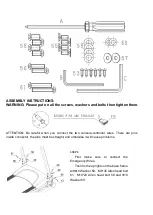
Page 6: ...hen you connect the two console controller wires There are pins inside connector the pins must be straight and otherwise it will cause problems STEP1 First make sure to connect the Emergency Wires Then fix the uprights on the base frame withФ8 Washer 60 M8 45 Allen head bolt 61 M10 20 Allen head bolt 58 and Ф10 Washer 59 ...

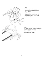
Page 7: ...ire of upright 2 Then fix the computer on the uprights with M8 20 Allen head bolt 55 M8 30 Allen head bolt 56 andФ8 Arc Washer 57 STEP3 Fix the left and right protective cover onto uprights with 4 2 15 Screw 53 Note 4 2 15 Screw have fixed onto the base frame and uprights already ...

Page 8: ...feet as shown by the arrow on the left side 2 Hold the top end covers as shown by the arrow on top left and pull the treadmill slowly down onto the ground To fold up the treadmill Hold the bottom end covers arrows showing in the left and right side and lift the treadmill ...

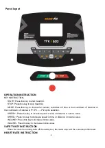
Page 9: ...own of calories or P1 P2 P12 cycle selection SPEED Press this key to increase speed or time or distance or calorie value SPEED Press this key to decrease speed or time or distance or calorie value INCLINE Press this key to increase incline value INCLINE Press this key to decrease incline value SAFETY KEY INSTRUCTION When the motor is running take off the safety key the motor stop and the console p...

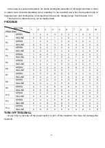
Page 10: ...5 6 7 8 9 10 P1 SPEED 1 2 2 3 3 3 3 2 2 1 INCLINE 0 0 1 1 2 2 1 1 0 0 P2 SPEED 1 2 2 3 4 4 3 2 2 1 INCLINE 0 0 2 3 4 4 3 2 0 0 P3 SPEED 1 2 2 3 4 4 3 2 2 1 INCLINE 0 0 3 7 4 4 7 3 0 0 P4 SPEED 1 2 2 3 3 3 3 2 2 1 INCLINE 0 0 3 7 4 4 7 2 0 0 P5 SPEED 1 2 2 3 4 4 3 2 2 1 INCLINE 0 0 2 4 6 8 4 2 0 0 P6 SPEED 1 2 2 4 4 6 4 2 2 1 INCLINE 0 0 3 4 5 7 7 3 0 0 P7 SPEED 2 3 4 6 6 9 6 4 4 2 INCLINE 0 0 2 4 ...

Page 11: ...GARLANDO SPA Via Regione Piemonte 32 Zona Industriale D1 15068 Pozzolo Formigaro AL Italy www everfit it info everfit it ...

Reviews: