background image


Value IP 288 / 368 / 468 Series


30


5.4.


Live View Window 

1

2

3

4

5

6

7

10

8

9

11


1.


Home


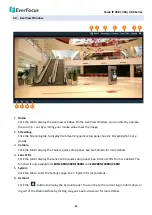
Click the tab to display the Live View window. On the Live View Window, you can directly operate 
the zoom in / out by scrolling your mouse wheel over the image. 

2.


Streaming


Click the Streaming tab to display the Streaming quick setup panel. See 

6.1 Streaming

 for more 

details.


3.


Camera


Click the tab to display the Camera quick setup panel. See 

6.2 Camera

 for more details. 

4.


Lens CTRL


Click the tab to display the Lens Control quick setup panel. See 

6.3 Lens CTRL

 for more details. The 

function is only available for 

EDN288M/368M/468M

 and 

EZN288M/368M/468M

5.


System 


Click the tab to enter the Settings page. See 7. System for more details. 

6.


Account 


Click the 

  button to display the Account panel. You can check the current log-in information, or 

log out of the Web interface by clicking Lougout. See 

6.4 Account

 for more details. 


Summary of Contents for 288 Series

Page 1: ...amera 2 Megapixel 288 Series 3 Megapixel 368 Series 4 Megapixel 468 Series User s Manual EBN288 368 468 EDN288M 368M 468M EMN468W EZN288 368 468 EMN468 EZN288M 368M 468M Copyright EverFocus Electronic...

Page 2: ...formation contained in this document is subject to change without notice Copyright All rights reserved No part of the contents of this manual may be reproduced or transmitted in any form or by any mea...

Page 3: ...ur in a particular installation If this equipment does cause harmful interference to radio or television reception which can be determined by turning the equipment off and on the user is encouraged to...

Page 4: ...t failure electric shock or in extreme cases fire 3 Cleaning For cameras with interchangeable lenses do not touch the surface of the sensor directly with the hands Use lens tissue or a cotton tipped a...

Page 5: ...Dynamic IP Address 25 5 2 Settings for Microsoft Internet Explorer 27 5 3 Connecting the Camera to the Network 28 5 4 Live View Window 30 6 Quick Setup Panel 32 6 1 Streaming 32 6 2 Camera 33 6 3 Lens...

Page 6: ...gs 55 7 2 2 Camera 56 7 2 3 Image 59 7 3 Event Settings 60 7 3 1 Event 60 7 3 1 1 Motion Settings 60 7 3 1 2 Tamper Detection Settings 62 7 3 1 3 Alarm Input 63 7 3 1 4 Alarm Output 65 7 3 1 5 Excepti...

Page 7: ...housing the Value IP 288 368 468 series meets a wide variety of needs for outdoor surveillance Except 12VDC power supply the series also supports Power over Ethernet IEEE 802 3af which eliminates the...

Page 8: ...ed Lens 1920 x 1080 Micro SD SDHC SDXC Max 128GB Yes T WDR Yes EZN368 2048 x 1536 Yes T WDR EZN468 2592 x 1520 Yes D WDR EZN288M 2 8 12mm Motorized Lens 1920 x 1080 Micro SD SDHC SDXC Max 128GB Yes T...

Page 9: ...tibility List http www everfocus com tw 5 Reset Button Press the button to restore the camera to factory default EMN468 EMN468W 1 2 3 4 6 2 3 4 6 5 No Item Name Descriptions 1 Light Sensor Detects lig...

Page 10: ...ghts 4 Lens Fixed lens 5 Reset Button Press the button to restore the camera to factory default 6 Micro SD SDHC SDXC Slot Insert a micro SD SDHC SDXC card Please go to the web page of the IP camera to...

Page 11: ...Value IP 288 368 468 Series 5 2 1 Dimensions EBN288 368 468 EDN288M 368M 468M EMN468 468W...

Page 12: ...Value IP 288 368 468 Series 6 EZN288 368 468 EZN288M 368M 468M...

Page 13: ...pending on scene IR reflectivity for EBN EDN EZN series models Extended IR range up to 10m 33ft Depending on scene IR reflectivity for EMN468 Multi streaming from H 265 H 264 1080p real time recording...

Page 14: ...1 x 1 x 1 x 1 7 Set Screw x 3 8 Power Pigtail Cable x 1 x 1 x 1 x 1 x 1 9 Accessories Instruction for installation of Set Screw x 1 10 Software CD x 1 x 1 x 1 x 1 x 1 11 Quick Installation Guide x 1 x...

Page 15: ...ilt in amplifier and external power supply are required 12VDC Input LAN PoE Cable Audio Input TRS Line in Red Audio Output TRS Line out White Alarm Input Black Reset Button Alarm Output RS 485 Red Vid...

Page 16: ...TRS Connector Left Channel Tip Right Channel Ring Ground Sleeve To activate the Audio function the Complex Stream must be selected See Stream in 7 2 1 2 Streaming Settings Pin Assignment Alarm Output...

Page 17: ...ing to the supplied Sticker and push the supplied four Screw Anchors into the four holes on the wall ceiling Drill another hole in the middle of the Sticker if you wish to run the wires into the wall...

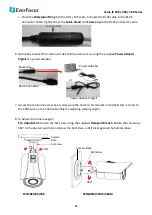
Page 18: ...the supplied four Screws to screw the camera base to the ceiling wall 6 Adjust the camera angle and twist back the Outer Housing simultaneously 7 Optionally screw back the Set Screw by using the supp...

Page 19: ...he Waterproof Ring into the LAN PoE cable Connect the RJ 45 cable to the RJ 45 Connector Cable Tightly screw the Cable Gland and Screw Cap to the RJ 45 Connector Cable 9 Optionally connect the camera...

Page 20: ...en drill a through wall hole for wiring the camera cables Push the supplied three Screw Anchors into the three holes on the wall ceiling Wall or Ceiling Sticker Anchors Screws 2 Unscrew the camera cov...

Page 21: ...J 45 Connector Cable 5 Optionally connect the camera to the 12VDC power source using the supplied Power Adapter Pigtail or a power adapter Power Adapter Pigtail Power Cable RJ 45 Connector or Power Ad...

Page 22: ...osition then tighten the rotate screw Due to the internal connector design it is recommended not to rotate the camera more than 30 30 30 Rotation screw Tilt Adjustment Loosen the two tilt screws and a...

Page 23: ...crew the camera base to the surface by using the supplied Screws Note that for EMN468W place the supplied Gasket between the camera base and the surface and then screw the camera base to the surface w...

Page 24: ...dapter 5 Access the camera live view See 5 Accessing the Camera Or using a video Test Out cable to connect a monitor to the Video Test Output on the camera for setting camera angles 6 To adjust camera...

Page 25: ...ing EZN288 368 468 EZN288M 368M 468M 2 You can wire the cables from the side of the camera or through the wall Wire the cables from the side of the camera Wire the cables through the wall 3 Place the...

Page 26: ...Power Adapter Pigtail Power Cable RJ 45 Connector or Power Adapter 7 Access the camera live view See 5 Accessing the Camera Or connect a handheld test monitor to the CVBS wire on the Cable Assembly f...

Page 27: ...8M 468M Note 1 Before start operating the IP camera please make sure the camera date and time are correct To configure the camera date time go to System Date Time setting page on Web UI 2 By default t...

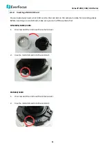
Page 28: ...t on the camera module for recording videos Before inserting a micro SD card make sure you turn off the camera first EDN288M 368M 468M 1 Unscrew and then remove the camera cover 2 Insert a micro SD ca...

Page 29: ...over on the bottom of the camera by loosening the screws 2 Insert a micro SD card into the card slot EZN288M 368M 468M 1 Loosen the two set screws on the bracket Set Screw 2 Loosen the three screws on...

Page 30: ...the edge of the housing Place the desiccant bag beside the IPC board Water proof ring Desiccant bag 6 Screw back the IPC board secure the rear housing back to the front housing and tighten the set sc...

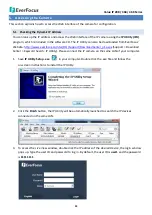
Page 31: ...Q Support DownloadCenter_p1 aspx Support Download Center Keyword Search IP Utility Please connect the IP camera on the same LAN of your computer 1 Save IP Utility Setup exe in your computer Double cli...

Page 32: ...168 0 10 5 To optionally configure the Machine Name IP Address IP Type or Port Number using the IPU a Log in the camera by checking the desired model and then click the Log in icon The Log in dialog b...

Page 33: ...hen first entering the remote web page of the device Go to C Program Files x86 Internet Explorer right click the browser and then click Run as administrator 2 You may need to turn User Account Control...

Page 34: ...te to see the IP camera on a LAN WAN Internet The camera must be assigned an IP address that is compatible with its LAN By setting up port forwarding on the router you can remotely access the cameras...

Page 35: ...his connection may require that you use DDNS for a reliable connection Please refer to Appendix E Setting up DDNS Function Cat 5 Straight Through Cable High speed modem Internet One to One Connection...

Page 36: ...ails 3 Camera Click the tab to display the Camera quick setup panel See 6 2 Camera for more details 4 Lens CTRL Click the tab to display the Lens Control quick setup panel See 6 3 Lens CTRL for more d...

Page 37: ...9 Local Settings 10 Two way Audio Click the Two way Audio buttons to switch the sound on off for the speakers and microphones if such external devices have been connected to the camera directly or via...

Page 38: ...mance between Real Time smaller value and Smooth way larger value Camera Title Type a name in the column to change the title Show Camera Title Check to show the camera title Format Select the encoding...

Page 39: ...value Select the Auto Gain Control level from Low to High see 7 2 2 Camera for more details The default AGC level is Mid High TWDR There are four value options Close Low Mid and High see 7 2 2 Camera...

Page 40: ...account panel Account Display the current user s login account Logout Click to log out of the Web interface 7 System Click the System tab on the Live View Window to enter the setting page Click the i...

Page 41: ...is type of address is stable and cannot change but the user has to make sure there are no address conflicts with other network connected devices DHCP Click the radio to enable DHCP This setting lets t...

Page 42: ...RTSP Port Use domain name to access and login device need mapping RTSP The default port number is 554 RTMP Port Use domain name to access and login device need mapping RTMP The default port number is...

Page 43: ...ess Fill in the multicast IP address IP addresses in the range of 224 0 0 0 through 239 255 255 255 are reserved for multicasting For devices you can use 225 x x x 232 x x x and 234 x x x 238 x x x Cl...

Page 44: ...t name from the DDS service provider s website We support these DDNS server providers www everfocusddns com members dyndns org ddns oray org dynupdate no ip com members 3322 org and www dnsdynamic org...

Page 45: ...in name from the DDNS server provider After complete the settings click Save to apply the changes Note 1 In order to support the full functionality of the camera you must open the port numbers 80 554...

Page 46: ...Time Display the device current time You can manually set up and click Apply to save the time setting Click PC to automatically adjust the camera s time by synchronizing with the PC After complete th...

Page 47: ...e Adjust box to enable adjusting the offset and set the desired minute in the min field After complete the settings click Save to apply the changes 7 1 2 3 DST Settings Enable Check the box to enable...

Page 48: ...ay Sunday from the Week drop down list to configure the schedule 3 Set up schedules to active the Schedule Record function Check the box of the desired section to configure the schedule and select a s...

Page 49: ...micro SD card information will be displayed in this field such as capacity available free space and record status To format the card click the Format button and all data saved on the micro SD card wi...

Page 50: ...Multi line Text Enter the desired text in the input field and check the Show box to display the text Time Format Check the OSD box to enable the Time Format function Select the desired time format fr...

Page 51: ...ng Firmware Using IP Utility Note 1 System updating should only be accomplished by trained staff 2 Do not disconnect power to the IP camera during the upgrade sequence The IP camera will reboot automa...

Page 52: ...eboot automatically every day at the specified time hh mm Every Week On the selected day the IP camera will reboot automatically at the specified time hh mm One Time The IP camera will reboot at the s...

Page 53: ...re changed and there is unexpected behavior Load Config Click to import a previously prepared configuration file and then apply the parameters from the configuration file to the system Restore This bu...

Page 54: ...camera The values cannot be changed on this page Device Type Display the device type The values cannot be changed on this page Firmware Version Display the current software version The values cannot b...

Page 55: ...rop down list The default authority for each group is listed below You can still configure the privileges for each account by clicking Authority Default Authority Admin Guest Operator Remote PTZ Yes Y...

Page 56: ...m the User Group drop down list 4 Click Save to save all the settings To delete a user account 1 Click the Delete button in the Operation column The following dialog box appears The following dialog b...

Page 57: ...om Pelco D or Pelco P Address Enter the address from 0 to 255 Baud Rate This field is to set the speed at which is used to transmit instruction or information through the RS 485 port reserved on the v...

Page 58: ...napshot Type the storage path for snapshots captured in the File page Backup file Type the storage path for recording files backed up in the Playback page Live View Recording Type the storage path for...

Page 59: ...dio to your computer if you have connected an external line in audio device to its audio Input Select an audio source currently only Line in is available then adjust the audio input output volume Note...

Page 60: ...ant the stream to stream a Constant Bit Rate or a Variable Bit Rate and set the values of whichever option you choose Bitrate For Constant Bit Rate only Select the desired Bit Rate from the drop down...

Page 61: ...rivacy Masks can be configured To set up a Privacy Mask 1 Check the Enable box to enable the Privacy Mask function 2 In the Area Settings field move the cursor to the position where you want the mask...

Page 62: ...nd white images with IR LED on based on the AGC value of the current video image Color Select to keep the camera in Day mode color images with IR LED off even in nighttime Black White Select to keep t...

Page 63: ...helps to reduce file size There are five value options OFF Low Mid Mid High and High The default 3DNR mode is Low Defogging The Defog function makes the subject appear clearer when the surrounding are...

Page 64: ...tomatic Note The Aperture function is only available for EDN288M 368M 468M and EZN288M 368M 468M Gamma Gamma Users can use this field to optimize video quality of the monitor Choose CURVE_1_6 CURVE_1_...

Page 65: ...The image will be rotated 270 degree Note Set up 90 180 270 degree rotation will cause the system to reboot automatically Please create a new network connection to the IP camera when the reboot is com...

Page 66: ...set up schedules to active alarm functions When a motion is detected by the camera the alarm icon at the top of the Live View window will turn red and blink to alert the user Up to four Motion areas...

Page 67: ...Email Check the box to enable transmitting the alarm notification to the mail server To configure Email settings see 7 3 2 1 Email Settings Snapshot Check the box to enable taking snapshots to the mic...

Page 68: ...drop down list to configure the schedule 3 Set up schedules to active the alarm functions and send alarm notification Check the box of the desired section to configure the schedule and select a start...

Page 69: ...o SD Card when an event occurs Alarm Output Check the box to enable triggering the external alarm device After complete the settings click Save to apply the settings Note The Snapshot and Record setti...

Page 70: ...ons for the Alarm Input channel Check the box of the desired reaction Email Snapshot Record or Alarm output to link with the function Email Check the box to enable transmitting the alarm notification...

Page 71: ...or Normally Close from the drop down list Output Delay Select the duration 5 seconds 10 minutes for the buffer This will determine the length of time after the event trigger moment that the external...

Page 72: ...gal Access Record Check the box to enable recording to the micro SD Card when an event occurs Alarm Output Check the box to enable triggering the external alarm device After complete the settings clic...

Page 73: ...PWD Type the password again to confirm it SMTP Server Enter the IP address or the host name of the SMTP server used to send e mails SMTP Port Enter the port number for SMTP Email Sending Interval Inpu...

Page 74: ...ted to the SD card slot To search and then play back the recording Check the CH01 box to select the IP camera on the left side panel and then select the date you want to search on the right side panel...

Page 75: ...or the backup files in the Up to column 4 Click Start to download the recording files click Stop to stop downloading Frame Play Click to play the recording file frame by frame Full Screen Click to dis...

Page 76: ...torage To search and then view the snapshot recording file 1 On the left side panel select the date you want to search and then click Search 2 Click the node of the desired file type to expand the sub...

Page 77: ...ded in the Home page Live View window Start Pause Click to play the file Click to pause playing Stop Click to stop playing Slow Click to slow down the play speed switch between 1 2 1 4 1 8 and 1 16 Fa...

Page 78: ...lect a log type from All Alarm Exception Settings Operation and Setup 2 Click on the Start End Time column to bring up the calendar and then select a start end date 3 Click the Search button the searc...

Page 79: ...w appears The IPU will automatically search the IP devices connected in the LAN 2 Log in the camera by checking the desired model and then click the Log in icon The Log in dialog box appears 3 Type th...

Page 80: ...s 74 4 Click the Upgrade Firmware button a browsing window appears 5 Select the firmware file evb and then click Open The IPU will automatically upgrade the firmware The camera will reboot once the up...

Page 81: ...DN288M 368M 468M EZN288M 368M 468M 2 2mm lens FOV 152 H x 83 V x 173 D EMN468W Lens Angle of View Horizontal 150 Vertical 75 Horizontal 360 Vertical 90 Horizontal 360 Vertical 90 Day Night True Day Ni...

Page 82: ...Input Output 2 1 Video Output Video Output cable Power Supply 12VDC PoE IEEE802 3af Class 3 Max Power Consumption IR LEDs on 12VDC 5 2W PoE 5 8W 12VDC 4 5W PoE 4 9W EMN468 12VDC PoE 7W EMN468W 12VDC...

Page 83: ...bling the Multicast Function The Multicast Function is a technique for one to many communication over an IP infrastructure in a network that is designed to share IP camera loading and reduce network b...

Page 84: ...468 Series 78 3 Go to the setting page of the router switch to enable the Multicast function Here we use a D Link DIR655 router and EverFocus 24 port switch for example 4 The Multicast function setup...

Page 85: ...he IP camera main is for Main Stream sub is for Sub Stream For example if the IP address of the IP camera is 192 168 37 55 the RTSP URL main stream sub stream of this IP camera will be Main Stream rts...

Page 86: ...ed Please follow the steps below Router Switch IP Camera Notebook Local Network Internet PC 1 Go to System System Settings Network IP Settings a Set up a static IP for the IP camera Type in the subnet...

Page 87: ...outer may look different in some ways however the concept of the port forwarding setting is the same For more details please consult the manual of your router Enter the IP address of the IP camera Ent...

Page 88: ...es not need to go through the trouble of checking if the IP address assigned by DHCP Server has changed Once the IP is changed the IP Camera will automatically update the information to the DDNS to en...

Page 89: ...the IP address subnet mask default gateway and the DNS Server Please consult with your ISP service provider for the information of subnet mask default gateway and the DNS Server If DHCP is selected Th...

Page 90: ...ed host name in the Domain field Note The host name should not include a space or a dot period or any special characters particularly _ c Click Save 4 The DDNS setup is now complete Open a browser and...

Page 91: ...EverFocus Japan 3F Kuramochi Building II 2 2 3 Koto Bashi Sumida Ku Tokyo 130 0022 Japan TEL 81 3 5625 8188 FAX 81 3 5625 8189 www everfocus co jp info everfocus co jp Your EverFocus product is design...

Reviews: