background image


5. Wire Connection   


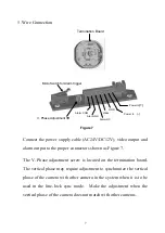
Connect the power supply cable (AC24V/DC12V), video output and 

alarm output to the proper connectors shown as Figure 7.   

The V. Phase adjustment screw is located on the termination board.    

The vertical phase may require adjustment to synchronize the vertical 

phase of the camera with other camera in the system when it is to be 

used in the line-lock sync mode.  Make the adjustment when the 

vertical phase of the camera does not match with other cameras.   


Termination Board 

Video 

Alarm COM 

Micro Switch for Alarm trigger 

GND 

Alarm NO 

Alarm NC 

Power In

(+)


V. Phase Adjustment VR 

Figure 7 

Power In 


(-)


Summary of Contents for 350HQ

Page 1: ...1 1 3 3 C Co ol lo or r R Ru ug gg ge ed d D Do om me e C Ca am me er ra a User s Manual and Operation Instructions EHD Series...

Page 2: ...make changes to the product specifications and documentation without notice All the components of the products including accessories components and outlook are based on the agreements of each deals t...

Page 3: ...Table of Contents Safety Warning 1 Introduction 2 Specification 3 Installation Instructions 4 Dip Switch Functions 8 Simple Instructions for the desiccant pack 11...

Page 4: ...he temperature range will stay between 40 to 50 3 Never face the camera toward the sun Never aim the camera at the sun or other extremely bright objects whether it is in use or not 4 Cleaning Do not t...

Page 5: ...L Revolutionary integrated 10 bit Digital Signal Processor DSP delivers excellent picture quality and performance Low light sensitivity of 0 5lux F 1 2 is achieved by using the advanced 1 3 interline...

Page 6: ...YES Auto gain control on off switch Back light comp on off switch Line Lock on off switch for 24VAC Flickerless on off switch Gamma correctio 0 45 Video output 1 0Vp p 75ohm Power source 12VDC 10 24V...

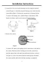
Page 7: ...nges can be easily removed from the bracket 2 Remove the camera To remove the camera first unplug the wire connection on the back of the camera Then loosen the 2 locking screws on the camera base push...

Page 8: ...re leaking into the housing apply an appropriate gasket or sealant around the conduit connection Conduit plug setscrew Side conduit entry Back conduit entry Mounting Setscrew Mounting Setscrew Mountin...

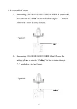
Page 9: ...e wall please to aim the Wall in line with the triangle marked on the lead frame factory default 2 If mounting COLOR RUGGED DOME CAMERA on the ceiling please to aim the Ceiling in line with the triang...

Page 10: ...he vertical phase may require adjustment to synchronize the vertical phase of the camera with other camera in the system when it is to be used in the line lock sync mode Make the adjustment when the v...

Page 11: ...is view angles as shown in Figure 8 Adjust the proper camera view angel as needed If a vari focal lens is used you may adjust the focus and zoom of the lens to bring the object in focus Be sure to loo...

Page 12: ...be driven by the AC signal in the power lines Note Line Lock sync mode operation is possible only when used with an AC power source it s not possible with a DC power source The default setting is ON...

Page 13: ...Flickerless Function On OFF When picture flicker fiercely turn FL on then the camera will stabilize the speed of electronic shutter at 1 100 NTSC or 1 120 PAL automatically and reduce the flicker imme...

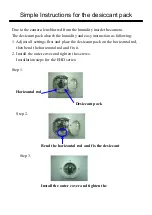
Page 14: ...t and place the desiccant pack on the horizontal rod then bend the horizontal rod and fix it 2 Install the outer cover and tighten the screws Installation steps for the EHD series Step 1 Step 2 Step 3...

Page 15: ...4 8838 www everfocus com European Office Albert Einstein Strasse 1 D 46446 Emmerich Germany TEL 49 2822 9394 0 FAX 49 2822939495 www everfocus de China Office Room 609 Technology Trade Building Shandg...

Reviews: