EAN7360 / EHN7360 / EZN7360
9
4.3.
I/O Terminal Block & Basic Connection
EAN7360
1
2
4
4
3
5
2
6
1.
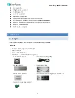
Use a standard network cable to connect the camera to the network.
2.
Connect the camera to power using one of the following methods:
Connect the camera to a 12VDC power source using the supplied Power Pigtail Cable.
Connect the camera to a 24VAC~ power source using the supplied Two-Pin Terminal Block.
Using the PoE function and the power will be provided over the network cable.
3.
Optionally connect the camera to a monitor using the supplied video Test-Out BNC cable.
4.
Optionally connect the camera to the speakers and microphones. Note that the audio input /
output features a line 3.5mm jack (TRS). Be sure to prepare speakers / microphones with TRS
connector. Also, speakers and microphones with a (built-in) amplifier and external power supply
are required. You can also use the built-in Microphone on the front panel of the camera (See
2.
Physical Description
for more details).
5.
Optionally use the I/O terminal block to connect the camera to the alarm in / out and RS-485
devices.
1 2 3 4 5 6
Pin Assignment
No. Function
No. Function
No. Function
1
Alarm COM (-)
3
Alarm Input (+)
5
RS-485+
2
Alarm Output (+)
4
Digital GND (-)
6
RS-485-
6.
Optionally insert the micro SD card into the card slot.
After powering the camera, the power LED will be lit in red and you can access the live view and adjust
the image clarity.

