background image


EAN7360 / EHN7360 / EZN7360


46


7.1.4.


Display and Overlay 

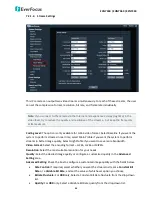
You can enable displaying camera information on the live view / backup images using this page. 


Title:

 Type a name in the column to change the title. 

Text Color:

 Select a color for the overlay information from the drop-down list.


Title:

 Check the box to display title. You can adjust the position of the title by the arrow buttons. 

Date / Time / Week:

 Check the boxes to display time information. You can adjust the position of the 

time information by the arrow buttons. 

Date Format:

 Select the desired date format from the drop-down list. 

Frame Rate / Bitrate: 

Check the box to display frame rate / bitrate. 

No. of Connections: 

Check the box to display the number of users connecting to the camera. 


After complete the settings, click 

Save

 to apply the changes. 


Summary of Contents for EAN7360

Page 1: ...Star Light Outdoor IR Network Camera EAN7360 EHN7360 EZN7360 Ultra Low Light Network Camera 3 Megapixel User s Manual EAN7360 EHN7360 EZN7360 Copyright EverFocus Electronics Corp Release Date May 2017...

Page 2: ...Information contained in this document is subject to change without notice Copyright All rights reserved No part of the contents of this manual may be reproduced or transmitted in any form or by any m...

Page 3: ...in a particular installation If this equipment does cause harmful interference to radio or television reception which can be determined by turning the equipment off and on the user is encouraged to t...

Page 4: ...failure electric shock or in extreme cases fire 6 Cleaning For cameras with interchangeable lenses do not touch the surface of the sensor directly with the hands Use lens tissue or a cotton tipped ap...

Page 5: ...Internet Explorer 27 5 3 Connecting the Camera to the Network 31 5 4 Live View Window 33 6 Quick Setup Panel 35 6 1 Streaming 35 6 2 Camera 36 6 3 Lens CTRL 37 6 4 Account 37 7 System 38 7 1 System S...

Page 6: ...2 7 3 1 Event 62 7 3 1 1 Motion Settings 62 7 3 1 2 Tamper Detection Settings 64 7 3 1 3 Alarm Input 64 7 3 1 4 Exception Settings 66 7 3 1 5 Continuous 67 7 3 2 Notification 69 7 3 2 1 Email Settings...

Page 7: ...sharpness Featured with a weather proof IP68 and vandal proof IK10 housing EHN7360 EZN7360 meets a wide variety of needs for outdoor surveillance The POLESTAR 3 megapixel series has a built in micro...

Page 8: ...more details 8 Audio In Connects to microphones In Speakers Out Note that the audio input output features a line 3 5mm jack TRS Be sure to prepare microphones speakers with TRS connector see TRS Conn...

Page 9: ...l Block Basic Connection 3 LAN PoE Connect to a 10 100 Ethernet or PoE 4 Micro SD SDHC Slot Insert a micro SD SDHC card see Appendix for tested card brands 5 Reset Button Press and hold the Reset Butt...

Page 10: ...ting a micro SD SDHC card 2 Reset Button Resets all configurations to the factory default settings Press and hold the Reset Button for 5 seconds 3 IR LEDs 44 IR LEDs for infrared illumination in night...

Page 11: ...cus for remote image adjustment EHN7360 EZN7360 P IRIS lens with a stepping motor for exact positioning to improve the IRIS performance EHN7360 EZN7360 Dual Streams from H 265 H 264 and M JPEG Ultra l...

Page 12: ...d Android EverFocus Genie XMS CMS ONVIF profile S compliant 4 Installation 4 1 Packing List Please check that there is no missing item in the package before installing EAN7360 EAN Series Camera lens n...

Page 13: ...e Quick Mounting Ring for LAN PoE cable for waterproofing through the wall installation Quick Mounting Ring x 1 Software CD x 1 MAC Address Sticker x 2 Quick Installation Guide x 1 Mounting Kit x 1 Lo...

Page 14: ...ick ESK1000 User s Manual PoE Switch EverFocus 5 8 16 24 Ports PoE Switch 5 Ports ES0501 40 8 Ports ES0812 31 ES0802 41 16 Ports ES1625 31 ES1645 51 24 Ports ES2426 31 ES2446 51 ES2448 62 Brackets BA...

Page 15: ...ra to the speakers and microphones Note that the audio input output features a line 3 5mm jack TRS Be sure to prepare speakers microphones with TRS connector Also speakers and microphones with a built...

Page 16: ...era module for easier wiring 2 Microphones and speakers with a built in amplifier and external power supply are required 3 2 1 6 5 4 9 8 7 12 11 10 16 15 14 13 Camera Module Pin Assignment No Function...

Page 17: ...or see TRS Connector image below Also microphones speakers with a built in amplifier and external power supply are required To activate the Audio function the Enable must be checked See 7 2 1 1 Audio...

Page 18: ...ter 3 Adjust the lens using the Focus Zoom Screws Note Installing a C mount lens without the C mount lens adapter may damage the camera sensor If you are using a DC Auto Iris lens 1 Remove the cover c...

Page 19: ...the camera body to support the camera EHN7360 Important Notice for the Installation If you want to mount the camera on the wall where direct sunlight may occur it is strongly recommended to mount the...

Page 20: ...er from the camera 2 Screw the Base Plate to the Wiring Box using the supplied four Phillips Screw Base Plate Wiring Box If you want to wire the cables through the bottom of the Camera Case follow the...

Page 21: ...he bottom of the Camera Case Cable Gland Camera Case c Screw the Circle Plate to the side hole on the Camera Case d Screw the Adapter Plate between the Base Plate and Wiring Box Base Plate Wiring Box...

Page 22: ...the Stopper depends on the number of cables inserted One Cable Conduit can only be inserted with one cable Plug Stopper Cable Conduit c Insert the network PoE cable through the Cable Conduit if your n...

Page 23: ...Cap 5 Connect the network PoE cable to the LAN PoE port on the camera module If you have difficulty connecting the network cable to the LAN PoE port on the camera module you can unscrew these two scre...

Page 24: ...the camera live view see 5 Accessing the User Interface To adjust the camera to a desired angle Pan Adjustment Simply turn left right for the top camera module 360 Tilt Adjustment Using the two tilt...

Page 25: ...lace the Quick Mounting Ring against the anchoring surface so that the holes line up Screw the Quick Mounting Ring to the wall using the supplied Long Screws 3 Screw the camera base to the Quick Mount...

Page 26: ...connector on the one end through the Screw Cap and Cable Gland c Crimp the RJ 45 connector onto the network cable Note that the wires should be placed into the RJ 45 connector based on the following o...

Page 27: ...mmediately in case of reducing the absorption capacity of the desiccant bag inside the camera 7 Stick the supplied Desiccant Bag inside the camera 8 Firmly close the camera cover for waterproofing and...

Page 28: ...w back the Set Screw Tilt Adjustment Loosen the Tilt Screw using the provided Hexagon Wrench and adjust the tilt angle by 90 Rotational Adjustment Loosen the Rotate Screws on both side of the camera b...

Page 29: ...lity Product eZ IP Software Tools IP Utility Download Please connect the IP camera on the same LAN of your computer 1 Save IP Utility Setup exe in your computer Double click the exe file and follow th...

Page 30: ...lete Please refer to 5 2 Settings for Microsoft Internet Explorer 5 To optionally configure the Machine Name IP Address IP Type or Port Number using the IPU a Log in the device by checking the desired...

Page 31: ...work administrators for configuration details 2 If you want to set up PPPoE please refer to 7 1 1 Network in the User s Manual To set up a static IP By default EverFocus IP cameras are set up with DHC...

Page 32: ...EAN7360 EHN7360 EZN7360 26 To show the Subnet Mask and Gateway items on the title bar right click the title bar to display the Customize Columns window select Subnet Mask and Gateway and then click OK...

Page 33: ...mputer 1 If error messages pop up when installing ActiveX in the Login page follow the steps below to fix the problem a When the error message Windows has blocked this software because it can t verify...

Page 34: ...ct Enable In the Download unsigned ActiveX controls field select Prompt In the Include local directory path when uploading files to a server field select Enable Click OK b When the error message An er...

Page 35: ...erface you may need to modify Internet Explore s security settings Open the Internet Explore click Tools Internet Options Security Tab Custom Level the Security Settings windows appears In the Include...

Page 36: ...s the camera after upgrading firmware you may need to clear the Internet Explore s cache Open the Internet Explore click Tools Internet Options General Tab in the Browsing history field click Delete C...

Page 37: ...to see the IP camera on a LAN WAN Internet The camera must be assigned an IP address that is compatible with its LAN By setting up port forwarding on the router you can remotely access the cameras fr...

Page 38: ...s connection may require that you use DDNS for a reliable connection Please refer to Appendix E Setting up DDNS Function Cat 5 Straight Through Cable High speed modem Internet One to One Connection Di...

Page 39: ...amera quick setup panel See 6 2 Camera for more details 4 Lens CTRL Click the tab to display the Lens Control quick setup panel See 6 3 Lens CTRL for more details The function is only available for EH...

Page 40: ...Audio Click the Two way Audio buttons to switch the sound on off for the speakers and microphones if such external devices have been connected to the camera directly or via the network To activate the...

Page 41: ...the encoding format H 265 or H 264 Resolution Select the most suitable resolution for your needs Bitrate kbps For CBR Slide the bar to adjust the customized Constant Bit Rate For VBR Slide the bar to...

Page 42: ...Auto ON IR you can further specify to turn on near or far IR LEDs use the buttons below For Auto IR you can further specify a mode to automatically switching day night in the Day Night Mode field und...

Page 43: ...ct an Iris mode from Auto or Manual For Manual use the Iris Open Iris Close buttons to adjust Iris Zoom In Zoom Out Use the buttons to adjust Zoom in or out Focus Near Focus Far Use the buttons to adj...

Page 44: ...EAN7360 EHN7360 EZN7360 38 7 System Click the System tab on the Live View Window to enter the setting page Click the item of the one you want to see in the setting menu to display the details...

Page 45: ...DHCP is not used you need to manually enter the IP address of the camera Do not enter an IP address that is already used for your computer or other network cameras Subnet Mask This field is used to s...

Page 46: ...ans you can directly connect the cameras listed in the networked device table by clicking on them Network Interface Card Select the type of your network interface card UPnP Mode Select an UPnP mode fr...

Page 47: ...0 0 0 through 239 255 255 255 are reserved for multicasting For devices you can use 225 x x x 232 x x x and 234 x x x 238 x x x Click here for more details Main Stream Multicast Video Audio Port Chang...

Page 48: ...tion please refer to Appendix E Setting up DDNS Function Before enabling the following DDNS function you should have applied for a host name from the DDS service provider s website We support these fo...

Page 49: ...the device data port which forwards to the external network port Network Port Mapping No Enter the device network port which forwards to the external network port Update Interval Select an interval fo...

Page 50: ...ly the changes 7 1 2 Date Time You can set up the system s time on this page 7 1 2 1 Date Time Settings There are three ways to configure the camera date and time synchronize with NTP synchronize with...

Page 51: ...k the SD Card utility or format the SD Card using this page Micro SD Card Information If a micro SD card has been inserted to the micro SD card slot of the camera the micro SD card information will be...

Page 52: ...ox to display title You can adjust the position of the title by the arrow buttons Date Time Week Check the boxes to display time information You can adjust the position of the time information by the...

Page 53: ...staff 2 Do not disconnect power to the IP camera during the upgrade sequence The IP camera will reboot automatically after the upgrade has completed 1 5 minutes 7 1 5 2 Auto Reboot You can manually re...

Page 54: ...nd a previously prepared configuration file Click the Load Configuration Server button to upload the file To export a configuration file Click to make a backup file of the machine s current configurat...

Page 55: ...TSC 60Hz or PAL 50Hz as video output format Language Select the preferred system language Firmware Version Display the current firmware version The values cannot be changed on this page Web Interface...

Page 56: ...configure all functions and parameters of the IP camera General User user2 user3 Operate bottom tool bar Snapshot Record Playback Two way Audio Microphone Live View Full Screen Fit to Screen on the Li...

Page 57: ...This field is the data bit at which you will be transferring Stop Bit This field is to set the stop bit for the RS 485 connection There are two different stop bits 1 or 2 Parity This field is to sele...

Page 58: ...CPU usage will be higher than normal File Size You can limit the size of each file recorded to PC in minutes Once you click the Record button on the Live View window the camera will start recording th...

Page 59: ...to its audio Input Check the Enable box to enable the camera s audio input function then adjust the audio source compression type input volume and output volume Note that the camera provides the line...

Page 60: ...if you want the system to perform streams in better image quality Select High Profile if you want to save more bandwidth Video Format Select the encoding format H 265 H 264 or MJPEG Resolution Select...

Page 61: ...gs to WAN default settings LAN Default Main Stream Sub Stream H 264 Rate Control VBR Quality Higher Bitrate 4096Kbps 1080p Frame Rate 25 GOP 75 Rate Control VBR Quality Average Bitrate 512Kbps Frame R...

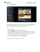
Page 62: ...ask 1 Check the Enable Mask box to enable the Privacy Mask function 2 Click the Draw Mask Area button On the preview window move the cursor to the position where you want the mask rectangle to start a...

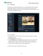
Page 63: ...ld To set up an ROI region 1 Click the ROI button on the left side then select a quality value for the ROI from the ROI Quality drop down list 2 Click the Set ROI button on the left side 3 Click the D...

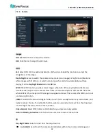
Page 64: ...dark areas simultaneously appear on the camera view There are two value options OFF and ON Note that when WDR is ON some parts of the image may appear solarized This is normal for WDR and is not a ca...

Page 65: ...witching time Enter the transition duration a switching from Night mode to Day mode will take from 0 to 60 second s D to N switching time Enter the transition duration a switching from Day mode to Nig...

Page 66: ...True Color Basic Mirror Select ON OFF to enable disable the Mirror function When Mirror is enabled the image will be rotated horizontally around a vertical axis Flip Select ON OFF to enable disable t...

Page 67: ...l Select to adjust the Red Green and Blue values below this field Anti falseColor The anti false color function can remove the moir pattern appears in high frequency part After complete the settings c...

Page 68: ...ns When a motion is detected by the camera the alarm icon at the top of the Live View window will turn red and blink to alert the user Up to four Motion areas can be configured To set up a Motion Dete...

Page 69: ...the drop down list Snapshot Check the box to enable taking snapshots to the micro SD Card when an event occurs You can further configure the Snapshot settings including Snapshot Interval and Snapshot...

Page 70: ...the button if you want the event reaction to be triggered only when both motion and tamper are detected After complete the settings click Save to apply the settings 7 3 1 3 Alarm Input To set up the...

Page 71: ...configure the Snapshot settings including Snapshot Interval and Snapshot No For example if you set up the Snapshot Interval to 5 and Snapshot No to 3 system will take 3 snapshots every 5 seconds E mai...

Page 72: ...I O Settings Select Normal Open or Normal Close from the drop down list Snapshot Check the box to enable taking snapshots to the micro SD Card when an event occurs You can further configure the Snapsh...

Page 73: ...otion Detection Click the button if you want the event reaction to be triggered only when both motion and out of focus are detected After complete the settings click Save to apply the settings 7 3 1 5...

Page 74: ...s to active the schedule record function Check the box of the desired section to configure the schedule and enter a start end time in the fields for the section 2 Specify to save the recordings to Ema...

Page 75: ...or select Other then enter a domain name To go back to the drop down list again click the left arrow button Sender Settings Check the box to configure the e mail sender settings You can select an ema...

Page 76: ...FTP server that is used to send recordings and snapshots from the camera to the preconfigured FTP server Note that to enable uploading to the FTP server function you have to check the FTP box of each...

Page 77: ...erver After complete the settings click Save to apply the settings Note If the camera lost connection to the FTP server the recordings will be automatically uploaded to the micro SD card on the camera...

Page 78: ...orage File Type and Date you want to search and then click Search 2 Search results will be displayed in the File List area Double click on the file or click the Play button to view the file 3 Click th...

Page 79: ...ng file Snapshot Click to take a snapshot Full Screen Click to display the current recordings in full screen Audio Click to adjust the volume or switch the sound on off for of the recording 7 4 2 Syst...

Page 80: ...The IPU will automatically search the IP devices connected in the LAN 2 Log in the camera by checking the desired model and then click the Log in icon The Log in dialog box appears 3 Type the Username...

Page 81: ...75 4 Click the Upgrade Firmware button a browsing window appears 5 Select the firmware file uot and then click Open The IPU will automatically upgrade the firmware The camera will reboot once the upgr...

Page 82: ...001 Lux F1 2 Black 0 0005 Lux F1 2 0 Lux F1 2 IR LEDs On Day Night True Day Night Shutter Time 1 25 1 8 000 IRIS DC IRIS P IRIS P IRIS Video Video Compression H 265 H 264 M JPEG Max Video Resolution 2...

Page 83: ...orage Micro SD SDHC card up to class 10 RS 485 RS 485 x 1 Alarm Input Output 1 1 Video Output BNC video test output cable Power Supply 12VDC PoE 24VAC Power over Ethernet IEEE802 3af Class 3 Max Power...

Page 84: ...0 No Image Displayed If the camera s image is not displayed on the web interface follow the steps below to fix the problem 1 Access the camera 2 In the Login page click the link to download the Activ...

Page 85: ...ttp www everfocus com tw download Support Download Enter keyword Storage Compatibility Table B Enabling the Multicast Function The Multicast Function is a technique for one to many communication over...

Page 86: ...cess to the Web UI of the IP camera to enable the Multicast function Click the Save button to save the setting System System Settings Network Multicast Settings 2 Go to the setting page of the router...

Page 87: ...this IP camera will be Main Stream rtsp 192 168 37 55 av0_0 Sub Stream rtsp 192 168 37 55 av0_1 D Setting up Port Forwarding Function IP Camera port forwarding can be used when users need to access a...

Page 88: ...nP box to enable the port forwarding function Click the Save button The default ports of all EverFocus IP cameras are as below You can change the port numbers if necessary Be sure the port numbers set...

Page 89: ...e this problem you can set up the DDNS function to your IP Camera and access your IP Camera with a fixed host name whenever the IP address of your IP Camera changes DDNS Dynamic Domain Name System is...

Page 90: ...local network enable either the Port Forwarding or DMZ function of your router Please refer to the manual of your router for more details Note If you enable the Port Forwarding of your router the Enab...

Page 91: ...with your ISP service provider for the information of subnet mask default gateway and the DNS Server If DHCP is selected The IP address subnet mask default gateway and the DNS Server will be assigned...

Page 92: ...ete Open a browser and enter the domain name http host name everfocusddns com in the address field The Web interface of the device should be displayed For example if you ve obtained the host name HQte...

Page 93: ...Japan 3F Kuramochi Building II 2 2 3 Koto Bashi Sumida Ku Tokyo 130 0022 Japan TEL 81 3 5625 8188 FAX 81 3 5625 8189 www everfocus co jp info everfocus co jp Your EverFocus product is designed and man...

Reviews: