background image

4

PRECAUTIONS

1.  Do not install the camera near electric or magnetic fi elds. 

Install the camera away from TV/radio transmitters, magnets, electric motors, transformers and audio speakers 
since the electromagnetic fi elds generated from these devices may distort the video image or otherwise 
interfere with camera operation.

2.  Never disassemble the camera beyond the recommendations in this manual nor 

introduce materials other than those recommended herein.  

Improper disassembly or 

introduction of corrosive materials may result in equipment failure or other damage.

3.  Try to avoid facing the camera toward the sun.  

In some circumstances, direct sunlight may 

cause permanent damage to the sensor and/or internal circuits, as well as creating unbalanced illumination 
beyond the capability of the camera to compensate.

4.  Keep the power cord away from water and other liquids and never touch the power 

cord with wet hands.  

Touching a wet power cord with your hands or touching the power cord with wet 

hands may result in electric shock.

5.  Never install the camera in areas exposed to oil, gas or solvents.  

Oil, gas or solvents may result in equipment failure, electric shock or, in extreme cases, fi re.

6. Cleaning

For cameras with interchangeable lenses, do not touch the surface of the sensor directly with the hands. Use 
lens tissue or a cotton tipped applicator and ethanol to clean the sensor and the camera lens. Use a damp 
soft cloth to remove any dirt from the camera body. Please do not use complex solvents, corrosive or abrasive 
agents for cleaning of any part of the camera.

7.  Do not operate the camera beyond the specifi ed temperature, humidity or power source ratings. 

This camera is suitable for indoor operation. Use the camera at temperatures within -10°C~50°C (14°F~122°F) and 
in an indoor environment; this device is not rated as weather proof. The input power source is 12VDC.


The use of 

properly fused or Class 2 power limited type supplies are highly recommended. 

8. Mounting

Use care in selecting a solid mounting surface which will support the weight of the camera plus any wind, 
snow, ice or other loading, and securely attach the camera to the mounting surface using screws and anchors 
which will properly support the camera. If necessary (e.g. when mounting to drop ceilings) use a safety wire to 
provide additional support for the camera. 

Summary of Contents for EBH5201

Page 1: ...Operation Instruction HDcctv 1080p Indoor Compact Bullet Camera EBH5201 EBH5201 006 EBH5201...

Page 2: ...e reference The information in this manual was current when published The manufacturer reserves the right to revise and improve its products All specifications are therefore subject to change without...

Page 3: ...osed to oil gas or solvents Oil gas or solvents may result in equipment failure electric shock or in extreme cases fire 6 Cleaning For cameras with interchangeable lenses do not touch the surface of t...

Page 4: ...use harmful interference to radio communications However there is no guarantee that interference will not occur in a particular installation If this equipment does cause harmful interference to radio...

Page 5: ...Table of Contents 1 PRODUCT OVERVIEW 7 1 1 FEATURES 7 1 2 ACCESSORY PARTS LIST 8 1 3 SPECIFICATIONS 9 1 4 DIMENSIONS 10 2 CAMERA COMPONENT DESCRIPTION 11 3 INSTALLATION 12 4 OSD Structure 14 6...

Page 6: ...much more No major upgrade to the IT network is required to deploy this powerful technology HDcctv cameras communicate at digital speeds up to 1 5Gb s over existing or new coaxial cable RG59 or other...

Page 7: ...mera Mounting Bracket Manual Screws Service Video Cable Please Note If an item appears to have been damaged in shipment replace it properly in its carton and notify the shipper If any items are missin...

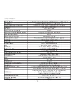
Page 8: ...d Auto Manual Selectable OSD Yes 5 axis joystick control D N Mode Auto Color B W Electronic D N Exposure Control Automatic Electronic Shutter DSS Low light boost 2X 3X 4X Lens Shading Compensation On...

Page 9: ...10 1 4 Dimensions Inches MOUNTING HOLE Top Bottom 1 4 20 UNC Depth 0 17 MOUNTING HOLE Top Bottom 1 4 20 UNC Depth 0 17 2 95 1 77 3 81 2 36 0 1 0 14 1 63 1 41 3 45...

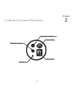
Page 10: ...11 2 Camera Component Description Chapter 2 OSD Control Joystick Service Video Connector HDcctv Out BNC Power LED DC12V Input...

Page 11: ...12 3 Installation Chapter 3...

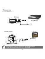
Page 12: ...and connectors are protected from humidity and other outdoor environments 13 NOTE Connections DC12V In BNC Female HDcctv Jack DC12V Adapter HDcctv DVR or other HDcctv Signal Equipment NTSC Video In Se...

Page 13: ...OW MIDDLE HIGH RED GAIN 0 20 BLUE GAIN 0 20 PUSH AUTO INITIAL RETURN BLC MODE OFF BLC BLC OSD OFF ON BLC X POSITION 0 20 BLC Y POSITION 0 20 BLC X SIZE 0 20 BLC Y SIZE 0 20 INITIAL RETURN DAY NIGHT D...

Page 14: ...0 40 X SIZE 0 40 Y SIZE 0 40 COLOR BLACK WHITE YELLOW CYAN GREEN MAGENTA RED BLUE TRANSPARENCY 100 75 50 25 0 INITIAL RETURN MOTION DETECT OFF ON RESOLUTION 0 4 SENSITIVITY 0 20 WINDOW USE ON OFF WIND...

Page 15: ...3 5625 8189 www everfocus co jp info everfocus co jp EverFocus Europe UK Unit 12 Spitfire Business Park Hawker Road Croydon Surrey CR0 4WD UK TEL 44 0 20 8649 9757 0845 430 9999 FAX 44 0 20 8649 9907...

Reviews: