Value IP 288 / 368 / 468 Series
14
b.
Insert a RJ-45 network cable (without the RJ-45 connector on the one end) through the
Cable Gland and Screw Cap.
c.
Place the Waterproof Ring into the LAN / PoE cable. Connect the RJ-45 cable to the RJ-45
Connector Cable. Tightly screw the Cable Gland and Screw Cap to the RJ-45 Connector
Cable.
4.
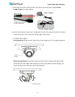
Optionally connect the camera to the 12VDC power source using the supplied Power
Adapter Pigtail or a power adapter.
Power Adapter Pigtail
Power Cable
RJ-45 Connector
or
Power Adapter
5.
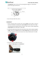
Access the camera live view. See 5. Accessing the Camera. Or using a video Test-Out cable to
connect a monitor to the Video Test Output on the camera for setting camera angles.


