7
PIR DETECTOR CONFIGURATION
1.
LED Selector:
J1
(3 PINS: Top, Center, Bottom)
A)
Top+Center w/black jumper:- testing mode: Light
Blinking
B)
Low w/black
jumper: Normal detection mode: No
light blinking while detecting
1.
To raise sensitivity turn clockwise
2.
To lower sensitivity turn counter clockwise
2.
Sensitivity Adjustment:
MAX
MIN
VR1
Detection range:
100
。
Wide angle/58 beams in 3
levels/Maximum coverage area:
35'x35'
Note: While adjusting you need to position LED selector as
indicated in (A)
To determine the time period of N.C/N.O relay to the alarm
panel/device
A)
Max time: Turn counter clockwise
B)
Min time: Turn clockwise
3.
Dwell Time Adjustment:
MIN MAX
VR2
Adjustable from 2 to 40 sec
Top + Center pins of "J4"must be selected to adjust the time
setting.
A)
Top + Center w/black jumper: Operate with "VR2" to
adjust time. (Sets the relay output to the alarm system,
DVR or other accessory according to individual
preference or application.
B)
Bottom w/black jumper: Relay output set for a
fixed 2 seconds.
4.
External Device Control:
(N.O or N.C)
J4
(3 PINS: Top, Center, Bottom)
Note: N.C/N.O relay output current: 2A24VDC, 2A 24VAC
Summary of Contents for ECMD200
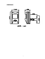
Page 4: ...3 DIMENSIONS...


