background image

- 11 - 


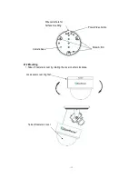
2.1.2 Mounting   

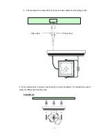
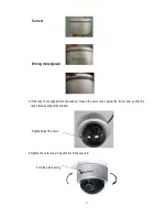
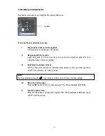
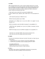
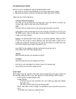
1. Take off camera’s cover by rotating the cover counter clockwise. 


Loose outer cover ring first 

Take off camera’s cover 

Power/Video Cable   

Camera base 

Screw A,B,C 

Wire outlet hole for   
Surface mounting 

Summary of Contents for ED610

Page 1: ...ilure or other damage 3 Try and avoid facing the camera toward the sun In some circumstances direct sunlight or may cause permanent damage to the sensor and or internal circuits 4 Keep the power cord...

Page 2: ...TION 10 2 1 Mounting Camera 10 2 1 1 Drill the Holes 10 2 1 2 Mounting 11 2 2 Adjusting Camera 13 2 2 1 Adjusting Camera Position 13 2 2 2 Adjusting Zoom and Focus 14 2 2 3 Camera Setting 16 2 2 3 1 O...

Page 3: ...LANCE CONTROL 25 3 6 DAY NIGHT 25 3 7 3DNR 26 3 8 SPECIAL 26 3 8 1 CAM TITLE 26 3 8 2 D EFFECT 27 3 8 3 MOTION 28 3 8 4 PRIVACY 29 3 8 5 SYNC 29 3 8 6 LANGUAGE 29 3 8 7 RETURN 29 3 9 ADJUST 29 3 9 1 S...

Page 4: ...st Color without compromise your choice of full motion color or true day night images in low light without ghosting True Day Night with ICR module Starlight super high sensitivity of 0 0002 Lux F 1 2...

Page 5: ...If an item appears to have been damaged in shipment replace it properly in its carton and notify the shipper If any items are missing notify your EverFocus Electronics Corp Sales Representative or Cu...

Page 6: ...m MV2 Back Light Comp OFF BLC HSBLC Selectable Auto Gain Control Off Low Middle High Selectable White Balance ATW AWB AWC Manual Indoor Outdoor Selectable Sync Mode Internal Line lock external sync Da...

Page 7: ...6 5 143mm 0 2 94 7mm 3 78 1 4 Dimensions 123mm x 107 8mm 4 8 x 4 2...

Page 8: ...7 1 5 Camera Component Description Exterior view Interior view Rotatable cover Outer Cover ring Base OSD joystick Power board...

Page 9: ...8 1 1 6 Front and Back Panel Layout Front Panel Layout Back Panel Layout 6 4 2 5 7 3...

Page 10: ...are 2 8 10mm 9 22mm 5 Power Video pigtail cable Connect power and video to pigtail cable 6 Test Video Output Connector When installing the camera you can use this video connector to connect a portabl...

Page 11: ...ee 2 2 4 Warning To prevent electrical shock turn off the electrical power before making electrical connections Do not expose the camera to water or moisture while open during installation nor try to...

Page 12: ...Mounting 1 Take off camera s cover by rotating the cover counter clockwise Loose outer cover ring first Take off camera s cover Power Video Cable Camera base Screw A B C Wire outlet hole for Surface...

Page 13: ...ected to the power and video cables from the ceiling or wall 3 Fix the camera base to ceiling or wall by using 3 screws and washers The washers are used to create the IP66 seal and must be used Ceilin...

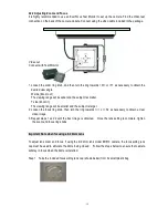
Page 14: ...nt 2 2 Adjusting Camera 2 2 1 Adjusting Camera Position Adjust the camera to best angle for viewing Module can be adjusted up and down When you install on the ceiling change angle of view by turning t...

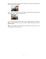
Page 15: ...ler and the subject is larger 2 Loosen the focus ring knob then turn the ring towards or N as necessary to obtain a clear video image 3 Repeat steps 1 and 2 until the best image is obtained Once the l...

Page 16: ...g the rings until subject is in focus Retighten the knobs when done Step 4 When finished adjusting focus and zoom remove the focus aiding cap from the camera lens replace the dome cover and secure the...

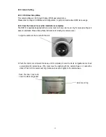
Page 17: ...ne outer cover ring for water proofing and ease of installation Please follow these instructions for closing the camera cover 1 Align the window in the cover with the lens 2 Push the interior cover to...

Page 18: ...lens is not aligned with the window loosen the outer cover adjust the inner cover so that the lens aimed exactly at the window 4 Tighten the outer cover ring until it is firmly secured Slightly adjust...

Page 19: ...e mode or value of a setting III Switching to sub menu screens When an item with sub menu is selected press inward on the end of the joystick to switch to the sub menu for further settings NOTE For th...

Page 20: ...19 3 2 ED610 Menu Tree...

Page 21: ...20...

Page 22: ...21...

Page 23: ...screen because of an irregular balance between illumination and scan frequency NTSC model 1 100 PAL model 1 120 3 4 2 AGC Auto Gain Control 1 Please direct the arrow to point to AGC by moving the joys...

Page 24: ...be adjusted The value adjustable is 0 6 HEIGHT Set the height of an area for the BLC to be adjusted The value adjustable is 0 6 Select RET to save all settings in this menu and returns to the previou...

Page 25: ...s 0 6 WIDTH Set the width of an area for the HSBLC to be adjusted The value adjustable is 0 6 TOP BOTTOM Set the Top Bottom side of an area for the HSBLC to be adjusted The value adjustable is 0 6 HEI...

Page 26: ...ddle of joystick Set the suitable color temperature and increase or decrease the red and blue color values at the same time while checking the color changes of the objects in view Select RET to save a...

Page 27: ...vious menu Select END to save all the menu settings and exit from the OSD menu 3 8 SPECIAL In this section user can control special settings including Cam Title D Effect Motion Privacy Sync Language a...

Page 28: ...2 D EFFECT 3 8 2 1 FREEZE Note that practical application of this feature requires direct access to the camera menu in real time OFF Select OFF to view moving pictures ON Select ON to view still pict...

Page 29: ...enables you to observe movements of objects in 4 different areas on the screen and the message MOTION DETECTED appears on the screen when movement is detected this may help to improve operational effi...

Page 30: ...OSD menu 3 8 5 SYNC There are two SYNCHRONIZATION modes INTERNAL and EXTERNAL LINE LOCK In LINE LOCK mode the video signal is synchronized to the frequency of the incoming AC power The Line Lock sync...

Page 31: ...o the previous menu Select END to save all the menu settings and exit from OSD menu 3 10 RESET 3 10 1 FACTORY RESET Reset to the default settings 3 10 2 RETURN Select RET to save all settings in RESET...

Page 32: ...product is designed and manufactured with high quality materials and components which can be recycled and reused This symbol means that electrical and electronic equipment at their end of life should...

Reviews: