background image


5

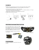
Installation 


Warning: 

To prevent electrical shock, turn off the electrical power before making electrical 

connections. OBSERVE POLARITY when connecting 12VDC power to the camera.  


1. Select mounting location. Open cover using tool provided.  
2. Place template and drill holes (5/8” minimum for wires, ~

¼”

 for hollow wall anchors; ~3/32” pilot 

hole for screws alone). Insert wall anchors if used.  

3. Mount camera to ceiling with 3 screws and adjust camera direction.  
4. Replace dome cover on base (snaps on). 


OSD Menu Controls and Video Test Point 
  

Press  the  Menu/Enter  button  to  bring  up  the  OSD 
menu.  Navigate  the  menu  with  the  direction  keys. 
Select  RETURN  to  move  back  to  the  previous  level 
menu.  When  exiting  the  main  menu,  choose  SAVE, 
NOT SAVE or RESET (factory defaults) as desired.  
 
Use adapter cable supplied to connect test monitor to 
video test point.  


Lens Adjustment 

Use fingers or screwdriver to adjust field of view (zoom) 
and focus. 


2. 

3. 

4. 

Summary of Contents for ED641

Page 1: ...ep the power cord away from water and other liquids and never touch the power cord with wet hands Touching a wet power cord with your hands or touching the power cord with wet hands may result in elec...

Page 2: ...field of view up to 82 wide or can magnify images for increased detail With dual voltage 12VDC 24VAC operation and low current draw this is the camera that you have been waiting for to create analog C...

Page 3: ...elays Min Illumination 0 01 lux nominal 0 lux with IR LEDs on IR LEDs 24 smart LEDs 850nm IR Range 82 feet depends on scene IR reflectivity Smart IR Control Off On with programmable area of interest a...

Page 4: ...75 Power Supply DC 12V AC 24V 10 Power Consumption DC12V 160mA Nominal 320mA IR ON AC24V 2W Nominal 4 5W IR ON Operating Temperature 14 F 122 F 10 C 50 C Storage Temperature 4 F 140 F 20 C 60 C Opera...

Page 5: ...l anchors if used 3 Mount camera to ceiling with 3 screws and adjust camera direction 4 Replace dome cover on base snaps on OSD Menu Controls and Video Test Point Press the Menu Enter button to bring...

Page 6: ...UAL COLOR TEMP MANUAL INDOOR OUTDOOR BLUE MANUAL 0 255 58 RED MANUAL 0 255 24 BACKLIGHT OFF OFF BLC AREA SEL AREA1 AREA2 AREA1 AREA STATE ON OFF ON GAIN 0 255 128 HEIGHT 0 10 005 WIDTH 0 10 004 LEFT R...

Page 7: ...F OFF HEIGHT 0 15 4 WIDTH 0 15 4 LEFT RIGHT 0 15 2 TOP BOTTOM 0 15 2 DEGREE 0 255 32 VIEW ON OFF ON PRIVACY OFF AREA 1 8 1 AREA STATE ON OFF ON HEIGHT 0 125 032 WIDTH 0 215 032 LEFT RIGHT 0 220 032 TO...

Page 8: ...MA 0 3 1 0 0 45 PED LEVEL 0 63 028 COLOR GAIN 0 255 192 NEG IMAGE ON OFF OFF LANGUAGE ENGLISH ENGLISH CHINESE1 ESPANOL POLISH DEUTSCH PORTUGUESE FRANCAIS JAPANESE VERSION 00 00 00 EXIT SAVE NOT SAVE R...

Page 9: ...ce Suite 803 Housefin Bhavan C 21 Bandra Kurla Complex Bandra East Mumbai 400051 India TEL 91 222 444 8791 FAX 91 222 444 8790 www everfocus in UK Office Unit 12 Spitfire Business Park Hawker Road Cro...

Reviews: