background image


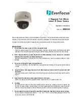
2  Megapixel  Full  HDcctv   

          Indoor  IR  Dome  Camera   


Operation  Instructions


Model  No. 

EDH5240


Please read this manual first for correct installation and operation. This manual should be retained for future 

reference. The information in this manual was current when published. The manufacturer reserves the right 

to revise and improve its products. All specifications are therefore subject to change without notice.   


PRECAUTIONS 
1.  Do not install the camera near electric or magnetic fields.   

Install the camera away from TV/radio transmitters, magnets, electric motors, transformers and audio 
speakers since the electromagnetic fields generated from these devices may distort the video image. 
 

2.  Never  disassemble  the  camera  beyond  the  recommendations  in  this  manual  nor  introduce 

materials other than those recommended herein.   

Improper  disassembly  or  introduction  of  corrosive  materials  may  result  in  equipment  failure  or  other 

damage. 


3.  Try and avoid facing the camera toward the sun. 

In some circumstances, direct sunlight  may  cause permanent damage to  the sensor and/or internal 
circuits. 


4. 

Keep the power cord away from water and other liquids and never touch the power cord with 
wet hands. 

Touching a wet power cord with hands or touching the power cord with wet hands may result in electric 
shock. 
 

5.  Never install the camera in areas exposed to water, oil or gas. 

Water, oil or gas may result in equipment failure, electric shock or, in extreme cases, fire. 
 

6.  Cleaning 

Do not touch the surface of the sensor directly with the hands. Use a damp soft cloth to remove any 
dirt from the camera body. Use lens tissue or a cotton tipped applicator and ethanol to clean the sensor 
and the camera lens. Please do not use complex solvents, corrosive or abrasive agents for cleaning. 
 

7.  Do not operate the camera beyond the specified temperature, humidity or power source ratings.   

Use the camera at temperatures within 0  ~ 40


(32

~104

)


and humidity between 20~80%. The 

input power source is 12VDC/24VAC. 


All manuals and user guides at all-guides.com

all-guides.com

Summary of Contents for EDH5240

Page 1: ...age 3 Try and avoid facing the camera toward the sun In some circumstances direct sunlight may cause permanent damage to the sensor and or internal circuits 4 Keep the power cord away from water and o...

Page 2: ...re 17 4 1 1 Lens 17 4 1 2 Shutter 18 4 1 3 AGC Auto Gain Control basic low light signal amplification 18 4 1 4 BLC 18 4 1 5 Anti Flicker 18 4 2 White Balance Control 18 4 3 Day Night 19 4 4 Special 19...

Page 3: ...of 20m 65 feet or more the EDH5240 easily accommodates a wide range of indoor applications while delivering stunning image quality 1 1 Main Features HDcctv 2 Megapixel real time 1920x1080 or 1280x720...

Page 4: ...or 720p60 for 60Hz systems 1080i50 1080p25 or 720p50 for 50Hz systems Main Output Connector BNC F Video Format Test Output NTSC PAL selectable 1V p p Test Output Connector Pin header adapter cable to...

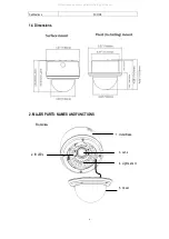
Page 5: ...4 Certifications FCC CE 1 4 Dimensions 2 MAJOR PARTS NAMES AND FUNCTIONS Front View 2 IR LEDs 4 Light sensor 1 Outer Base 3 Lens 5 Cover All manuals and user guides at all guides com...

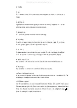
Page 6: ...shipped from the factory This base is used for surface mounting and is discarded for flush mounting 6 Focus Adjust 8 HDCC TV Video Output 9 Power Input 7 Zoom Adjust 10 Video Test Output 11 OSD menu...

Page 7: ...ary and re tighten when the adjustment is complete 8 HDcctv Video Output Please connect to the BNC connector of the cable from the HD DVR or HDcctv monitor 9 Power Input Please connect this connector...

Page 8: ...ngle to the desired direction With this unique 3 axis positioning system installers can capture images from virtually any angle without compromising performance Loosen this screw manually to rotate th...

Page 9: ...ow 2 Use the appropriate tool to drill the INNER holes and a clearance hole for the power and video wires Note The minimum recommended material thickness is 1 cm 3 Use the plastic anchors and push the...

Page 10: ...adapter to power wire if needed 6 Take a long Phillips pan head screw with a washer and tighten it into a plastic anchor Repeat the same step until all the 4 screws are fixed to the wall 7 Attach pow...

Page 11: ...ved in the earlier step Preposition camera so it is facing approximately in the desired direction 9 Attach video test cable to test point on rear of camera module Aim and focus the camera Remove test...

Page 12: ...r to the drilling template below 2 Use the appropriate tool to drill the OUTER holes carefully cut along the dashed circle to create a clearance hole for the inner base unit Note The minimum recommend...

Page 13: ...to detach the inner base from the outer base Set aside the outer base 6 Screw the 2 spring tabs in the orientation shown to the slots at both sides of the inner base using the 4 Philips head screws pr...

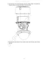
Page 14: ...and push excess wire back into hole Fold the spring tabs up 8 Preposition camera so it is facing approximately in the desired direction 9 Push the entire inner base into ceiling while holding the spri...

Page 15: ...bs will open automatically to support the camera against the ceiling 11 Use the long Phillips pan head screws x4 provided to screw the base to the ceiling Do NOT use washers All manuals and user guide...

Page 16: ...ar on the monitor II Navigating with the joystick Angle the joystick or to move the cursor up or down Angle the joystick or to adjust the mode or value of a setting III Switching to sub menu screens W...

Page 17: ...rn Auto WB One push WB Red 0 100 Manual Blue 0 100 White Balance Return Indoor Outdoor Return Auto Color Day Night Black White Return 720p60Hz 720p50Hz Resolution 1080i60Hz 1080i50Hz 1080p30Hz 1080p25...

Page 18: ...ng Exposure White balance Day Night Special and Image adjust Please select the item by moving the joystick UP or DOWN then press SET to enter the settings Move the joystick to the last option which is...

Page 19: ...when manual lens is used 4 2 White Balance Control The screen color can be adjusted by using the White Balance function Please select one of the 5 modes below by moving the joystick UP or DOWN then pr...

Page 20: ...or DOWN then press SET to enter the settings Select Return to return to the previous menu 4 4 1 Resolution 1 Select camera resolution from 720p60Hz 1080i60Hz or 1080p30Hz when TV output format is NTS...

Page 21: ...versa A negative color image is additionally color reversed with red areas appearing cyan greens appearing magenta and blues appearing yellow 4 4 3 3 Test Pattern Select Test Pattern On or Off by movi...

Page 22: ...IGHT The contour of the video image becomes cleaner and more easily distinguished as the level of Sharpness increases If the level is set too high it may affect the video image and cause noise The ava...

Page 23: ...info everfocus co jp EverFocus Europe UK Unit 12 Spitfire Business Park Hawker Road Croydon Surrey CR0 4WD UK TEL 44 20 8649 9757 44 845 430 9999 FAX 44 20 8649 9907 www everfocusuk co uk salesuk ever...

Reviews: