E V E R F O C U S E L E C T R O N I C S C O R P O R A T I O N
5
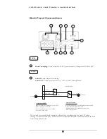
Back Panel Connections
Audio IN:
Audio input for recording.
Audio OUT:
Audio output can be set to “ON” or “OFF” in Setup Menu.
When in recording or standby mode, the out of
SW1 is connected to Audio IN.
Playback Audio
When in playback mode the out of SW1 is
connected to SW2 Audio.
When Playback Audio is enabled then the output of SW2
will be connected to Playback Audio.
When Playback Audio is disabled then there is no
audio output (MUTE).
2
Operation of SW1:
Operation of SW2:
Audio IN
Audio OUT
OFF / Mute
SW1
SW2
A
( Internal circuit )
5
2
4
7
9
6
1
10
3
8
POWER
AUDIO
1
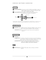
When Audio Out is enabled and machine is in Recording or Standby mode, the Audio IN is loop-
through to Audio Out connector. When Audio Out is enabled and machine is in Playback mode then the
Audio Out playback audio.
Main Power plug:
Connect the DC12~24V power source to Adapter for AC100~240V.
Summary of Contents for EDSR400H
Page 1: ...Instruction Manual E ED DS SR R4 40 00 0H H Volume 1 ...
Page 66: ...E V E R F O C U S E L E C T R O N I C S C O R P O R A T I O N 62 ...
Page 67: ...E V E R F O C U S E L E C T R O N I C S C O R P O R A T I O N 63 ...
Page 68: ...E V E R F O C U S E L E C T R O N I C S C O R P O R A T I O N 64 ...
Page 85: ...E V E R F O C U S E L E C T R O N I C S C O R P O R A T I O N 81 ...
Page 91: ...E V E R F O C U S E L E C T R O N I C S C O R P O R A T I O N 87 ...
Page 95: ...91 ...
Page 96: ...92 ...
Page 97: ...93 Remote Control Appendix A ...
Page 98: ...94 Time Lapse Mode Recording Time Appendix B ...
Page 99: ...95 ...
Page 100: ...96 Alarm Board Configuration Appendix C ...
Page 101: ...97 ...
Page 102: ...98 ...
Page 106: ......
Page 107: ......


