background image


5

5. Disconnect the power and video wire from the camera board end of the wire (1x 4 pin white connector) 

and the 2 power wires from the power board attached to the base plate (1 x 2 pin connector with blue 

marking and 1 x 2 pin connector with white color). Gently pull the wires out from under the plate until 

they are free. Using wrench or pliers, remove the weather tight bushing from the rear conduit hole. Using 

the plug removed in step 3 above, close the rear conduit hole (additional caulk or other sealant 

recommended).     


6. Pass the camera end of the power/video cable through side conduit hole. Using wrench or pliers, 

carefully tighten the weather tight bushing into the side conduit hole.   


7. (Optional) Pass the power/video wires under the base plate and up through the center hole. 


8. Position the power/video wires so that they don’t interfere with the camera module and carefully 

attach the 4 pin white connector to the camera board, being sure to position the connector so it fits 

properly onto the tiny pins within. Next, attach the blue 2 pin connector and the white 2 pin connector to 

the matching color receptacles on the power board. 

NOTE: the 2 pin blue connector goes into the 

receptacle marked in blue on the power board.

 Failure to properly attach these connectors may 

permanently damage the camera. 


General Connection and Setup 

1.


Connect the power cord to DC 12V or AC 24V power supply   


2.


Use 75 ohm type coaxial cable to connect the camera to a monitor or DVR.   


Summary of Contents for EHD363

Page 1: ...er disassembly or introduction of corrosive materials may result in equipment failure or other damage 3 Try to avoid facing the camera toward the sun In some circumstances direct sunlight may cause pe...

Page 2: ...NR 2D Noise Reduction and Anti CR Anti Color Rolling insure optimum image quality under low or unbalanced lighting conditions Vandal Proof materials and an IP66 weather resistant housing allow reliab...

Page 3: ...solution 700 TV line Sensitivity 0 01Lux F1 4 0Lux IR S N Ratio More than 54 dB Electronic Shutter 1 60s 1 100 000s Video Output BNC F 1 0Vp p 75 Gamma Correction 0 45 Lens Type Vari Focal 3 7 12mm F1...

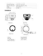
Page 4: ...O D x H 142mm x 115 5mm 5 6 x 4 55 Weight 979 g 2 16 lbs Certifications CE FCC DIMENSIONS A Lens B IR LED C Side conduit entry D Back conduit entry Dimensions Front View Bottom View Bottom View D E F...

Page 5: ...teps 1 Use the security wrench provided to loosen the 4 screws holding the dome cover 2 Remove the dome cover IF REAR WIRE MUST BE REMOVED RELOCATED SEE STEPS 4 8 Attach the camera body to the mountin...

Page 6: ...n the weather tight bushing into the side conduit hole 7 Optional Pass the power video wires under the base plate and up through the center hole 8 Position the power video wires so that they don t int...

Page 7: ...cover with the lens Attach the dome cover to dome base with the 4 mounting screws NOTE The cover only goes on in ONE direction There is a key and slot if not aligned cover will not close properly NOT...

Page 8: ...8189 www everfocus co jp info everfocus co jp EverFocus Europe UK Unit 12 Spitfire Business Park Hawker Road Croydon Surrey CR0 4WD UK TEL 44 20 8649 9757 44 845 430 9999 FAX 44 20 8649 9907 www ever...

Reviews: