background image

Analogue IR speed dome series 


10

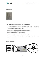
1. Shift the Joystick up/down or right/left to view from camera. 

2. Turn the top of the Joystick to zoom in/out. 

3. Press Zoom In/Out, Focus F. /N. and IRIS +/- function keys to operate the EPTZ860. 


1.6.


Packing List 

There are main body with a camera module, housing with a base board, bracket, power adapter, 

Manual, plus one tool packet in the package. The detail accessories are listed below: 

Standard 


Camera Main Body x1 


Bracket x1 


Housing x1   


Tool packet 


RS485 Terminal Block 


1 desiccant packs 

1.7.


Cable Needed 


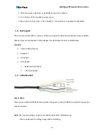
Power Cable 

Power source with 24VAC/25W max

.

provides the power to the EPTZ860. An extension power line 

may be needed. 


Note:

 The input AC voltage range of an adapter depends on different area. 

            Please make sure the voltage range before installing. 


Summary of Contents for EPTZ Series

Page 1: ...Speed Dome EPTZ Series USER MANUAL Copyright EverFocus Electronics Corp Release Date Aug 2013...

Page 2: ...g 11 Communication Protocol Setting 15 Transmission Speed Setting Baud Rate Setting 15 1 9 Bracket and Speed Dome Installation 16 Installation Requirements 16 EPTZ860 Speed Dome Camera Wall Mount Simp...

Page 3: ...S 22 1 11 3 PATTERN 23 1 11 4 PRIVACY ZONE 23 1 11 5 OTHER 23 1 11 6 ALARM 25 1 13 Camera 26 1 14 IR 26 1 13 0 IR MODE 27 1 13 1 OUTPUT POWER 1 9 27 1 13 2 TESTING TIME 02S 15S 27 1 13 3 STANDBY POWER...

Page 4: ...Analogue IR speed dome series 4 1 17 Reset 29 1 18 Exit 29...

Page 5: ...on Auto white balance function creates natural shades of color Auto iris adjusts the monitoring image to the best brightness Support 360 degree horizontal rotation range and 94 degree tilt rotation ra...

Page 6: ...Product Model EPTZ860 Pickup Device 1 3 SONY 960H CCD Scanning System NTSC or PAL Min Illumination Color 0 2 LUX B W 0 01 LUX 0LUX IR LED On S N Ratio AGC OFF 52dB Electronic Shutter Auto 1 50 1 10 00...

Page 7: ...6Preset positions Pattern 4PCS Communication RS485 Bus Communication Protocol EVF 1 Pelco D Pelco P Baud Rate 1200 2400 4800 9600bps Alarm 4 inputs and 2 outputs Optional Environmental Rating IP66 for...

Page 8: ...Function direction list Pin Function 1 ALMIN1 Alarm Input 1 2 ALMIN2 Alarm Input 2 3 ALMIN3 Alarm Input 3 4 ALMIN4 Alarm Input 4 5 GND Alarm input Common 6 ALARM NC OUT Alarm Output Normal Close 7 AL...

Page 9: ...to connect cables by the following steps 1 Connect the RS 485 cable to EPTZ860 and a keyboard EKB500 2 Connect a video cable from EPTZ860 to a monitor 3 Connect the power to the EPTZ860 and a keyboard...

Page 10: ...with a base board bracket power adapter Manual plus one tool packet in the package The detail accessories are listed below Standard Camera Main Body x1 Bracket x1 Housing x1 Tool packet RS485 Termina...

Page 11: ...confirmed before the dome is installed The control related setting that is address communication protocol and transmission speed have to be set consistently with the control device such as a keyboard...

Page 12: ...s RS 485 ID address show on the speed dome White part represents the switch key For example for EVF protocol white keys are all switched downward for ID Address 0 white keys are all switched downward...

Page 13: ...3 Switch Address Switch Address Switch Address Switch Address Switch Address Switch Address ON 1 2 3 4 5 6 7 8 Switch Address 65 ON 1 2 3 4 5 6 7 8 66 ON 1 2 3 4 5 6 7 8 67 ON 1 2 3 4 5 6 7 8 68 ON 1...

Page 14: ...2 3 4 5 6 7 8 191 Switch Address Switch Address Switch Address Switch Address Switch Address Switch Address ON 1 2 3 4 5 6 7 8 Switch Address 193 ON 1 2 3 4 5 6 7 8 194 ON 1 2 3 4 5 6 7 8 195 ON 1 2 3...

Page 15: ...tches to ON the speed dome EPTZ860 will enter a self test mode Transmission Speed Setting Baud Rate Setting The 4th and 5th bits on the PCB board are used to set the Baud Rate The default baud rate se...

Page 16: ...e agent and should comply with all local regulations Service personnel should expect potential problems such as surface strength surface material falling objects outer breaches building vibration or o...

Page 17: ...3 Connect the cable you detached from base board to the RS485 cable Power cable and video cable you thread from the wall or ceiling RS485 cable has to be connected via a terminal block If you need to...

Page 18: ...for mounting the bracket base 5 Screw in 4 long screws to fix the bracket to bracket base Note The camera module on the mechanical part is very sensitive Please be careful when installing this part 6...

Page 19: ...amera Setup Menu In this section setup and operation guide of EPTZ860 will be introduced There are 9 items of the setting menu 1 10 Structure of the Setup Menu Press MENU to enter camera setup menu Tu...

Page 20: ...eft Right to enter COMM SET sub menu see diagram 3 3 diagram 3 3 SYSTEM DOME CAMERA IR DISPLAY TIME LANGUAGE RESET EXIT SYSTEM DOME CAMERA IR DISPLAY TIME LANGUAGE RESET EXIT DEVICE ID 0000 9999 CHECK...

Page 21: ...999 Default value is 1185 b CHECK ID 0000 9999 Default value is 0 c TARGET ID d BAUD TATE 1 12 Dome In main menu turn joystick Up or Down to select DOME option Press Enter key or turn joystick Left Ri...

Page 22: ...1 11 2 GUARD TOURS a GUARD TOUR NO 1 b CALL GUARD TOUR C GUARD TOUR Press Enter key of keyboard to enter GUARD TOURS sub menu diagram 3 6 PRESET SCAN GUARD TOURS PATTERN PRIVACY ZONE OTHER ALARM EXIT...

Page 23: ...to enter OHTER sub menu diagram 3 8 a PARK MODE NONE PATTERN 1 TOUR 1 360SCAN AB SCAN PRESET 1 PRESET 8 PRESET SCAN GUARD TOURS PATTERN PRIVACY ZONE OTHER ALARM EXIT PRESET PRESET NO 001 CALL PRESET S...

Page 24: ...8 Press Enter key of keyboard to enter POWER ON ACT sub menu diagram 4 0 d RATIO SPEED ON OFF The default is ON Press Enter key of keyboard to enter RATIO SPEED sub menu NONE PATTERN1 TOUR1 360SCAN AB...

Page 25: ...s ON OFF The default is ON EXIT PARK MODE PARK TIME POWER ON ACT RATIO SPEED AUTO FLIP EXIT ON The default is ON OFF The default is ON EXIT PARK MODE PARK TIME POWER ON ACT RATIO SPEED AUTO FLIP EXIT...

Page 26: ...ck down PRESET 1 PRESET 16 g ALARM 4 PR OFF PRESET 1 PRESET 16 1 13 Camera 1 14 IR In main menu turn joystick Up or Down to select IR option Press Enter key or turn joystick Left Right to enter IR sub...

Page 27: ...agram 4 5 1 13 1 OUTPUT POWER 1 9 1 13 2 TESTING TIME 02S 15S 1 13 3 STANDBY POWER 1 9 1 13 4 STANDBY TIME 15S 30S 1 13 5 ILLUMINATION ON 00L 25L 1 13 6 IR SWITCH ZOOM 0 20 1 13 7 AMBIENT LIGHT 37L IR...

Page 28: ...FF 1 14 1 ZOOM ON OFF 1 14 2 P AND T ON OFF 1 14 3 ACT ON OFF 1 14 4 TIME ON OFF 1 14 5 IR ON OFF 1 15 Time DATE TIME SCHEDULE 1 16 Language In main menu turn joystick Up or Down to select LAGUAGE opt...

Page 29: ...7 0 CAM DATA 1 17 1 SYS DATA 1 17 2 FACTORY DEFAULT 1 17 3 CALIBRATION a Off b 1D 15D the default is 15D 1 18 Exit Select Exit to save settings and exit from current page SYSTEM DOME CAMERA IR DISPLAY...

Page 30: ...llection systems for used electrical and electronic product Please help us to conserve the environment we live in Ihr EverFocus Produkt wurde entwickelt und hergestellt mit qualitativ hochwertigen Mat...

Reviews: