background image


EPTZ3602/3602i 

40 


4.7


System


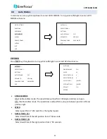
In main menu, turn joystick Up/Down to select SYSTEM. Turn joystick Left/Right to enter SYSTEM 
sub-menu. 


1.


AUTO INIT: Select auto initiation time from OFF, DAILY, WEEKLY. Speed dome will automatically initiate 
and return to the previous position by maintaining all the settings you have done.   

2.


LANGUAGE: Select language. The current version only supports English version. 

3.


PASSWORD: Press Enter key or turn joystick Left/Right to enter password sub-menu.   


-PASSWORD ACTIVE: Select YES to activate password mode. Select NO to disable password mode.   
-ENTER PASSWORD: Enter the password. 
-VERIFY PASSWORD: Enter the password again to confirm your input.   
Press IRIS+ key to save and return to previous menu. Press IRIS- key to cancel. 
-SAVE AND RETURN: Turn joystick Left/Right to save the changes and return to previous menu.   
-RETURN: Turn joystick Left/Right to return to previous menu without saving changes. 

4.


LOAD DEFAULT: Press Enter key to load default values, all values will return to factory default value.   

5.


Restart: Press Enter key to restart the speed dome.   

6.


EXIT: Exit from current menu.   


VIDEO SETTINGS 

POSITIONS 

OSD/AREAS 

AUTO MODES 

ALARM 

PRIVATE ZONES 

SYSTEM 

INFO 

EXIT 


AUTO INIT 


OFF 

LANGUAGE   

ENGLISH 

PASSWORD 

<┘ 

LOAD DEFAULT  [PUSH ENT] 

RESTART  

[PUSH ENT] 

EXIT 

PASSWORD 

PASSWORD ACTIVE 

NO 

ENTER PASSWORD 

XXXX 

VERIFY PASSWORD 

XXXX 


SAVE AND RETURN   


RETURN 

AUTO INIT 


OFF 

LANGUAGE   

ENGLISH 

PASSWORD 

<┘ 

LOAD DEFAULT  [PUSH ENT] 

RESTART  

[PUSH ENT] 

EXIT 

Summary of Contents for EPTZ3602

Page 1: ...EPTZ3602 3602i Speed Dome 36x 960H IP66 ICR DNR WDR Fan Heater User s Manual Copyright EverFocus Electronics Corp Release Date August 2014...

Page 2: ...nts of this manual may be reproduced or transmitted in any form or by any means without written permission of the EverFocus Electronics Corporation EverFocus 12F No 79 Sec 1 Shin Tai Wu Road Hsi Chih...

Page 3: ...t occur in a particular installation If this equipment does cause harmful interference to radio or television reception which can be determined by turning the equipment off and on the user is encourag...

Page 4: ...or in extreme cases fire 6 Cleaning For cameras with interchangeable lenses do not touch the surface of the sensor directly with the hands Use lens tissue or a cotton tipped applicator and ethanol to...

Page 5: ...Installation 7 3 5 2 1 Replacing the Desiccant Bags 7 3 5 3 Initial Setup 8 3 5 4 Wall Mount Installation 12 3 5 5 Ceiling Mount Installation 15 3 5 6 EKB500 Connection 19 4 Configuration in the OSD...

Page 6: ...pan tilt speeds ranging from 360 per second to 0 01 per second with 0 1 position accuracy for fast and accurate monitoring A maximum of 192 preset points can be configured for precise location of targ...

Page 7: ...acking List There are 3 boxes that are camera main body with a camera module top housing with a base board pin connector and outer housing with bubble plus one tool packet in the package The detail ac...

Page 8: ...mount adapter Used for installing a wall mount bracket to a pole indoors or outdoors Indoor ceiling pendant mount bracket Used for installing a speed dome against a ceiling Outdoor sunshield Indoor re...

Page 9: ...oltage Be sure to check the voltage range in your area before installing Video Cable A BNC cable is used for connecting an EPTZ3602 EPTZ3602i to a DVR or a monitor An amplifier may be needed depending...

Page 10: ...video cable Pin15 16 are RS 485 pin for connecting to keyboard Pin 17 and 18 are power pin for connecting to 24 VAC power 1 12 Alarm 13 14 Video 15 16 RS485 17 18 24VAC EPTZ3602 3602i Base Board Pin F...

Page 11: ...h all local regulations Service personnel should check potential problem such as surfaces strength surface materials falling objects outer breaches building vibration and other similar conditions Chec...

Page 12: ...the Desiccant Bags 1 On the Top Housing slightly press the black plastic socket backward and lift up the base board 2 Remove the desiccant bags from the top housing 3 Stick the supplied 3 new desiccan...

Page 13: ...up the DIP Switch The new values will only take effect after restarting the camera DIP Switch Camera Main Body ID Address The ID address of the camera should be set to correspond properly with the co...

Page 14: ...Address Switch Address Switch Address Switch Address Switch Address Switch Address ON 1 2 3 4 5 6 7 8 Switch Address 65 ON 1 2 3 4 5 6 7 8 66 ON 1 2 3 4 5 6 7 8 67 ON 1 2 3 4 5 6 7 8 68 ON 1 2 3 4 5...

Page 15: ...6 7 8 191 Switch Address Switch Address Switch Address Switch Address Switch Address Switch Address ON 1 2 3 4 5 6 7 8 Switch Address 193 ON 1 2 3 4 5 6 7 8 194 ON 1 2 3 4 5 6 7 8 195 ON 1 2 3 4 5 6...

Page 16: ...d on the sticker The default protocol is EVF DIP Switch Sticker on the Camera Main Body Note If you switch the three protocol switches to ON the camera will enter a self test mode Baud Rate The fourth...

Page 17: ...hole for inserting the camera cables You can optionally drill a second through wall hole to separate cable feeding see Step 3 2 Attach the waterproof silicon pad to the bracket base plate for waterpr...

Page 18: ...power cables through the top hole of the base board If necessary connect the alarm cable as well using the bottom hole 5 Screw the bracket base to the wall using the 4 screws 6 Screw the wall mount br...

Page 19: ...g lines up with the red triangle on the outside of the main body Push the main body upward into the top housing until the orange catches on both sides click into position Top Housing Main Body Note 1...

Page 20: ...via any IP network 3 5 5 Ceiling Mount Installation It is required to use the optional Indoor Recessed Mount Bracket and Surface Ring to attach the camera to the ceiling for supporting the camera s w...

Page 21: ...rom the indoor recessed mount bracket 4 Place and then screw the camera s top housing on the top disk of the indoor recessed mount bracket by using the 3 short screws Top Disk 5 Use a cable or other m...

Page 22: ...re the red triangle on the inside of the top housing lines up with the red triangle on the outside of the main body Push the main body upward into the top housing until the orange catches on both side...

Page 23: ...it clockwise 10 Slide the surface ring to the fillister and slightly turn it until it is firmly fixed Note When you turn on the power the camera will enter self inspection mode and run a self testing...

Page 24: ...onnect the EKB500 Keyboard to the EPTZ camera RJ 45 Cable Connector Box Blue Orange Black Red White Black Yellow Green RS 485 RS 485 EPTZ Series 1 EPTZ Series 32 RS 485 RS 485 EKB500 1 Connect the EPT...

Page 25: ...shift the camera view in that direction 2 Twist the top of the Joystick to zoom in out 3 Press the Zoom In Out Focus F N or IRIS to manually operate these functions 4 To enter the OSD menu of the EPTZ...

Page 26: ...ter the OSD root menu Move the Joystick left right to enter the sub menu diagram 3 1 4 1 Video Settings In main menu turn joystick Up Down to select VIDEO SETTINGS Turn joystick Left Right to enter VI...

Page 27: ...ONE PUSH Press the Enter key to fine tune the camera focus DIGITAL ZOOM Digital zoom enable or disable ON Enable the digital zoom OFF Disable the digital zoom WHITE BALANCE White Balance has the follo...

Page 28: ...ill be disabled and increase the infrared sensitivity ICR ON At a certain level of brightness the IR cut filter will reactivate automatically ICR OFF COLOR In Color we define color of the image Select...

Page 29: ...star sign will appear next to the number When finished go to RETURN and tilt the joystick left right to go to the Preset options VIDEO SETTINGS POSITIONS OSD AREAS AUTO MODES ALARM PRIVATE ZONES SYSTE...

Page 30: ...t speed DWELL TIME S Select the dwell time in second for the preset position from 1 to 99 FOCUS MODE Select focus mode for the preset position from MANUAL ONE PUSH and AUTO WHITE BALANCE Select the wh...

Page 31: ...zone and name it when the speed dome turns to the zone you set it will display zone name on the screen only if OSD AREAS Display Zone is set as YES Tilt the joystick up and down to scroll through the...

Page 32: ...t go to CLR and press Enter key DIRECTIONS Press Enter key of keyboard or turn joystick Left Right to enter DIRECTIONS sub menu ZONE1 MOVE TO LEFT POSITION IRIS SAVE AND NEXT STEP IRIS CANCEL DIRECTIO...

Page 33: ...or turn joystick Left Right to enter DISPLAY sub menu see diagram 3 14 SHOW OSD ON Show OSD of Camera Title Directions Zones Preset Title Motion Zoom and Fan OFF Do not show OSD 2 SEC Show OSD for 2 s...

Page 34: ...show zoom multiple FAN YES Show fan indication when fan is enabled NO Do not show fan indication MOTION YES Show motion message when a motion occurs NO Do not show motion message when a motion occurs...

Page 35: ...d position right SPEED Select speed from 1 255 and 255 is the highest speed DWELL TIME L S Select dwell time of the left position from 1 99 seconds DWELL TIME R S Select dwell time of the right positi...

Page 36: ...ard to save setting and return to previous menu Note When Left Right Position are set the speed dome will patrol between each position DEFAULT ON All settings in AUTOPAN menu will be returned to defau...

Page 37: ...joystick Left to go previous page or turn joystick Right to go next page 6 RETURN Turn joystick Left Right to return to previous menu PATTERN Press Enter key of keyboard to enter PATTERN sub menu Note...

Page 38: ...you set 5 When you return to PATTERN SETUP menu turn the joystick Left Right to PLAY Press Enter key of keyboard The camera starts to run the pattern tour you set The camera keeps playing the pattern...

Page 39: ...Turn the joystick Left Right to select the mode to resume to It is selectable from PREV MODE POS 1 H TOUR1 PAT 1 and AUTOPAN POWER UP FUNC Turn the joystick Left or Right to select the mode to return...

Page 40: ...close alarm input NO Enable a normal open alarm input NIGHT NC Set camera at night mode with normal close alarm input When there is event triggered the camera will be changed to day mode NIGHT NO Set...

Page 41: ...ey to select tour number Turn joystick Left or Right to make selection It is selectable from1 16 Press Enter key again to confirm selection 4 DURATION Duration of alarm input TIMEOUT Turn the joystick...

Page 42: ...t triggered when a motion event is detected Select NO to disable this function 7 SYSTEM ERROR Select YES to have alarm output triggered when system error occurs Select NO to disable this function 8 RE...

Page 43: ...to 8 There is a color frame showing you the motion detection area you change Motion 1 is represented by pink Motion 2 by blue Motion 3 by green and Motion 4 by yellow Press IRIS key to save setting an...

Page 44: ...one position Press IRIS to save and return to previous menu 4 Zone color select private zone area color 5 Exit exit from current menu VIDEO SETTINGS POSITIONS OSD AREAS AUTO MODES ALARM PRIVATE ZONES...

Page 45: ...the password again to confirm your input Press IRIS key to save and return to previous menu Press IRIS key to cancel SAVE AND RETURN Turn joystick Left Right to save the changes and return to previou...

Page 46: ...This counter counts the preset movement and 1 is counted when the speed dome runs to preset position 6 X CONT X axis counter This counter counts the x axis movement and 1 is counted when the speed dom...

Page 47: ...Low Mid High Dynamic Noise Reduction Yes OFF Low Mid High White Balance Indoor Outdoor ATW AWB Wide Dynamic Range Yes OFF ON Motion Detection Yes OFF ON Privacy Zone Masking Yes 4 zone Video Output 1V...

Page 48: ...rotocols AUTO EVF Pelco P Pelco D Plus D A Type Panasonic Address Editable Yes through DIP switch Speed Dome ID Address 0 255 Power Source 24 VAC Power Consumption 30W Max Weather Resistant IP66 rated...

Page 49: ...o pan speed 1 239 Press Enter to start auto pan In order to set the two points press Set A Pan and then enter the dwell time 1 127 seconds of each point The EPTZ camera begins to pan from point A to p...

Page 50: ...speed 1 239 dwell time 1 239 seconds and the title of the position Shift the joystick Right Left to change bits and shift the Joystick Up Down to change the alphanumeric characteristic The available a...

Page 51: ...ess Enter Switch the Joystick up down to select a position or a tour enter a position or tour number and then press Enter to confirm the alarm link setting If you set the position number to 99 the dom...

Page 52: ...co jp info everfocus co jp EverFocus China Shanghai Room 403 Ruijin Business Center No 96 Zhaojiabang Road Luwan district Shanghai 200020 China TEL 86 21 6471 2229 6471 2291 FAX 86 21 6471 0566 www e...

Reviews: