EPTZ9200/9300 Series
2
2.
Cables and I/O Terminal Block
Cable Descriptions
Power Cable
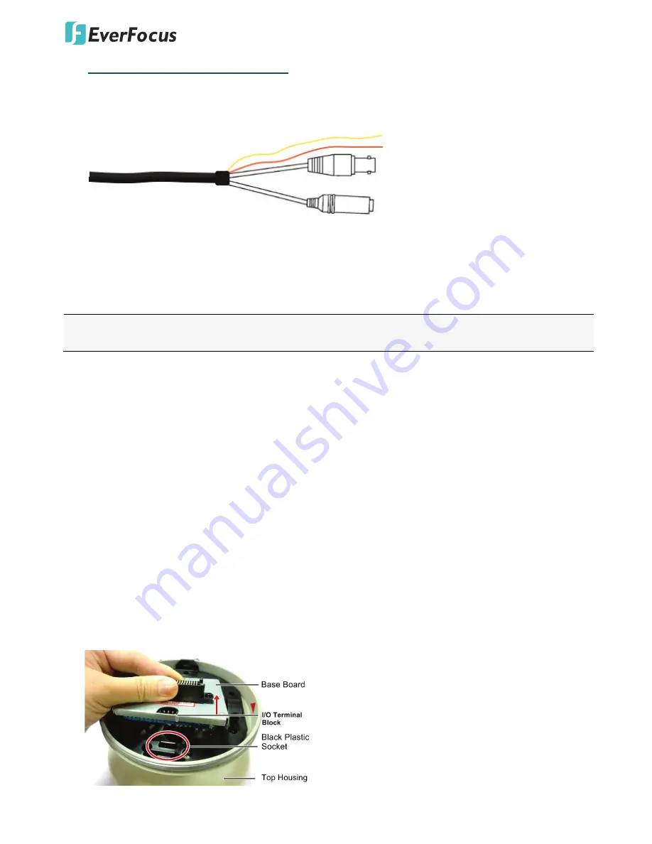
An adapter with 24 VAC~ / 3A output provides the power to the EPTZ9200/9300 Series camera. An
extension power line may be needed.
Note:
Different regions may use different ranges for AC voltage. Be sure to check the voltage range in your
area before installing.
Video Cable
A BNC cable is used for connecting an EPTZ9200/9300 Series to a DVR or a monitor. An amplifier may be
needed depending on the distance.
RS-485 Cable
The yellow wire carries RS-485+, and the orange wire carries RS-485-. Connect these wires to the EKB500 or
other control device in order to control the PTZ camera.
I/O Terminal Block
The base board that is inside the top housing connects to power cable, video cable, control cable, alarm
cable and fan. The housing must be removed in order to properly connect the cables. The connectors of
cable names are marked on the board in white text.
There are 4 alarm inputs and 2 alarm outputs available, represented by Pin 1~12. Pin 13 and 14 are video
pins for connecting to video cable. Pin15~16 are RS-485 pin for connecting to keyboard. Pin 17 and 18 are
power pin for connecting to 24 VAC~ power.
Orange RS485-
24VAC~
(POWER)
VIDEO
Yellow RS485+


