background image

- 18 - 

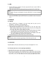
HEIGHT: Set the height of an area for the BLC to be adjusted. The value adjustable is 0~6. 
 
RETURN:  
Press “RET” to save all settings in the BLC menu and return to the previous menu. 
Press “END” to save all the menu settings and exit. 


5.4.6


BLC/HSBLC


HSBLC 

(

Highlight Suppression BLC

is used to reduce the brightness of light sources in a specific area. 

It is activated only in a low illumination environment to minimize the effects of glare from bright lights 
such as spotlights, street lights or headlights in the field of view. Where ‘traditional’ BLC can increase 
the exposure of a dark area surrounded by a brighter area, HSBLC can decrease the exposure of bright 
areas surrounded by darker areas.   
 
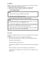
1. Please direct the arrow to point to “BLC” by using the UP and DOWN buttons.   
2. Select the HSBLC mode by pressing the LEFT or RIGHT button. Then make adjustments as below: 
 

LEVEL: Adjust the sensitivity level for HSBLC from 0 to 8.   

 
DEFAULT: Set the factory default values for HSBLC.   
 
LEFT/RIGHT: Set the Left/Right side of an area for the HSBLC to be adjusted. The value 
adjustable is 0~6. 
 
WIDTH: Set the width of an area for the HSBLC to be adjusted. The value adjustable is 0~6. 
 
TOP/BOTTOM: Set the Top/Bottom side of an area for the HSBLC to be adjusted. The value 
adjustable is 0~6. 
 
HEIGHT: Set the height of an area for the HSBLC to be adjusted. The value adjustable is 0~6. 
 
RETURN:  
Press “RET” to save all settings in the HSBLC menu and return to the previous menu. 

  Press “END” to save all the menu settings and exit 


5.4.7


D-WDR 


When there are both bright and dark areas at same time, this function can make both areas properly 
exposed.  

1. 

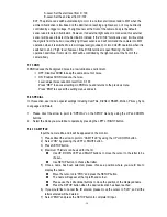
Please direct the arrow to point to “D-WDR” by using the UP and DOWN buttons.   

2.    Select the mode you would like to operate by moving the joystick LEFT or RIGHT. 

OFF: Disables D-WDR function 
INDOOR: Select this option if you are in an indoor environment. 
OUTDOOR: Select this option if you are in an outdoor environment.   


Summary of Contents for EQ610

Page 1: ...equipment failure or other damage 3 Try and avoid facing the camera toward the sun In some circumstances direct sunlight may cause permanent damage to the sensor and or internal circuits 4 Keep the power cord away from water and other liquids and never touch the power cord with wet hands Touching a wet power cord with hands or touching the power cord with wet hands may result in electric shock 5 N...

Page 2: ...nd connections 6 3 INSTALLATION 9 4 RS 485 CONNECTION 10 5 CAMERA SETUP OPERATIONS 11 5 1 Setup Buttons 11 5 2 Display Close the user setup menu screen 12 5 3 LENS 16 5 4 EXPOSURE 16 5 4 1 SHUTTER 16 5 4 2 BRIGHTNESS 16 5 4 3 AGC Auto Gain Control basic low light signal amplification 16 5 4 4 SENSE UP 17 5 4 5 BLC BLC 17 5 4 6 BLC HSBLC 18 5 4 7 D WDR 18 5 4 8 Return 19 5 5 WHITE BALANCE CONTROL 1...

Page 3: ... 5 8 3 RS 485 22 5 8 4 MOTION 22 5 8 5 PRIVACY 23 5 8 6 SYNC 23 5 8 7 LANGUAGE 23 5 8 8 RETURN 23 5 9 ADJUST 23 5 9 1 SHARPNESS 23 5 9 2 BLUE 23 5 9 3 RED 23 5 9 4 RETURN 24 5 10 RESET 24 5 10 1 FACTORY RESET 24 5 10 2 RETURN 24 5 11 EXIT 24 6 HOW TO CONTROL AN EQ610 BY A KEYBOARD 24 ...

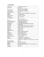
Page 4: ...wer sources to satisfy user s different needs 1 1 Main Features Super HAD II sensor at 05 lux has 5X better native light sensitivity before DSP low light boost Color without compromise your choice of full motion color or true day night images in low light without ghosting True Day Night with ICR module Optional Starlight super high sensitivity of 0 0002 Lux F 1 2 is achieved through a sensitivity ...

Page 5: ...nual Indoor Outdoor Selectable Sync Mode Internal Line lock Day Night Auto Color BW EXT Ext port for switch on command OSD menu Multiple functions local or RS 485 remote control 3D DNR Off On switchable Digital WDR Outdoor Indoor Digital Slow Shutter Sens Up to 256X Mirror Off Mirror V Flip Rotate Selectable Digital Zoom Off On selectable up to 32X Motion Detection Off On for 4 selectable zones Pr...

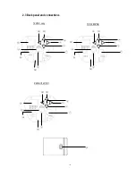
Page 6: ...details 2 2 Top Bottom Mounting Using the two phillips head screws provided the mounting bracket may be mounted to the top of the camera body for suspending the camera or the brackets may be mounted to the bottom of the camera body to support the camera Bottom Bracket Top Bracket Light Sensor TAKE CARE NOT TO OBSTRCUT THIS OPENING WITH THE BODY OF THE LENS ...

Page 7: ... 6 2 3 5 6 7 8 9 10 11 4 11 9 2 3 5 6 7 4 12 10 8 2 3 5 6 7 8 9 10 11 4 10 10 2 3 Back panel and connections 1 1 12VDC only 100 240VAC 1 24VAC 12VDC ...

Page 8: ...tead of the internal AGC level to control any color to B W switching examples of possible EXT control devices are an external light level sensor such as the one mounted in the front face of the camera an auxiliary light sensor mounted external to the camera or a control voltage applied to the D N In terminal If the D N In terminal is used it will override the signals from the built in or auxiliary...

Page 9: ... 10 Audio Output Connector for audio model only 11 Ext Sensor If a user wants or needs to change the location of the EXT that is external and independent of the camera s internal AGC circuit light level sensor they can use an External light sensor to connect to this port Note External light sensor kit is an optional product Part ETHPES 01GR When this External sensor port is used and EXT is selecte...

Page 10: ...lens cable to the auto iris lens connector on the side of the camera 5 After mounting and connecting the camera when making final focus adjustments remove the protective sheets from both sides of the ND filter provided place the ND filter in front of the lens to force the lens iris to open then adjust the lens focus until the best image is obtained 6 Lock the lens focus by turning any clamping scr...

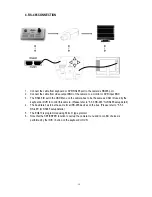
Page 11: ...to be the same as CAM ID used by the keyboard or DVR to control this camera Please refer to 5 5 3 RS 485 for RS485 setup detail 4 The baud rate has to be the same for all RS 485 devices on the bus Please refer to 5 5 3 RS 485 for RS485 setup details 5 The EQ610 is programmed using Pelco D type protocol 6 Note that the SET ENTER function to call up the camera menu and to confirm choices is performe...

Page 12: ... is used to move the cursor upwards Use this button to select the desired item 3 Set Menu Button This button is used to enter the setup menu If the item has its own sub menu indicated by press this button again to display the sub menu 4 Right Button Use this button to select or adjust the parameters of the selected item The parameter changes each time this button is pressed 5 Down Button This butt...

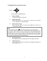
Page 13: ...u screens the last item choice is either RETURN or END Selecting this choice and then pressing the LEFT or RIGHT arrow buttons will toggle this choice between RETURN and END RETURN will exit the current menu to the next higher menu END will close the current menu and EXIT the menu system If you have completed all changes choose END otherwise choose RETURN to continue setup Pressing the SET button ...

Page 14: ... 13 EQ610 Menu Tree ...

Page 15: ... 14 ...

Page 16: ... 15 ...

Page 17: ...r balance between illumination and frequency NTSC model 1 100 PAL model 1 120 AUTO Shutter speed is automatically controlled depending on the brightness of the screen This option is available when a manual iris lens is selected above 3 Select RETURN and press the SETUP button when you finish all the settings 5 4 2 BRIGHTNESS Adjust the brightness of the screen manual lens only The level can be adj...

Page 18: ...et the factory default values for BLC LEFT RIGHT Set the Left Right side of an area for the BLC to be adjusted The value adjustable is 0 6 WIDTH Set the width of an area for the BLC to be adjusted The value adjustable is 0 6 TOP BOTTOM Set the Top Bottom side of an area for the BLC to be adjusted The value adjustable is 0 6 NOTE 1 When SHUTTER is in manual mode SENSE UP will be disabled 2 When AGC...

Page 19: ...LEVEL Adjust the sensitivity level for HSBLC from 0 to 8 DEFAULT Set the factory default values for HSBLC LEFT RIGHT Set the Left Right side of an area for the HSBLC to be adjusted The value adjustable is 0 6 WIDTH Set the width of an area for the HSBLC to be adjusted The value adjustable is 0 6 TOP BOTTOM Set the Top Bottom side of an area for the HSBLC to be adjusted The value adjustable is 0 6 ...

Page 20: ... checking the color changes of the objects in view Press RET to save all settings in this menu and return to the previous menu Press END to save all the menu settings and exit INDOOR Select this option when the color temperature is 5 600 K OUTDOOR Select this option when the color temperature is 3 300 K Press RET to saves all settings in this menu and returns to the previous menu Press END to save...

Page 21: ...from 0 100 Press RET to saves all settings in DNR menu and returns to the previous menu Press END to save all the setting menus and exit 5 8 SPECIAL In this section user can do special settings including Cam Title D Effect RS485 Motion Privacy Sync Language and Return 1 Please direct the arrow to point to SPECIAL on the SETUP menu by using the UP and DOWN buttons 2 Select the mode you would like t...

Page 22: ...m from X1 0 up to X32 Note that zoom levels above X4 may lead to excessive pixellation To control the portion of the magnified image in view 0 is the center of the image Pan Select digital pan from 100 to 100 Tilt Select digital tilt from 100 to 100 Return Press RET to saves all settings in D ZOOM menu and returns to the previous menu Press END to save all the setting menus and exit 5 8 2 4 GAMMA ...

Page 23: ...ovements of objects in 4 different areas on the screen and the message MOTION DETECTED appears on the screen when movement is detected and a Motion Alarm voltage trigger output is provided at the rear of the camera this feature may help to improve operational efficiency The camera detects an object s movement by sensing changes in the pixels displayed OFF Disables the MOTION function ON AREA SELEC...

Page 24: ...he video signal is synchronized to the frequency of the incoming AC power The Line Lock synchronization can only be used when the supply power is 24VAC 60Hz NTSC models or 50Hz PAL models INT Internal synchronization L L External line lock synchronization 5 8 7 LANGUAGE Select OSD language EQ610 camera supports multiple languages including English Japanese Traditional Chinese and Simplified Chines...

Page 25: ...p menu 3 Move the joystick to select or adjust the parameters of the selected item The parameter changes each time as the item is selected by joystick 4 Move the joystick to select or adjust the parameters of the selected item The parameter changes each time as the item is selected by joystick Note 1 When remotely controlled using RS 485 the SET ENTER button function is equivalent to the bit patte...

Page 26: ...Focus product is designed and manufactured with high quality materials and components which can be recycled and reused This symbol means that electrical and electronic equipment at their end of life should be disposed of separately from your household waste Please dispose of this equipment at your local community waste collection recycling centre In the European Union there are separate collection...

Reviews: