EZN1160/1260/1360
9
6.
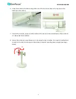
Screw the camera to the Stand using either one of the four holes (two on the top; two on the
bottom) on the camera.
7.
Connect the network, power and other cables of the camera to the related devices. Please refer to
3.1 Cables and Terminal Block
.
8.
Access the camera live view. Please see
5. Accessing the User Interface
. Or connect a handheld test
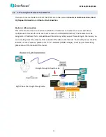
monitor to the Video Test Output on the camera module for adjusting camera angles (see image
below).
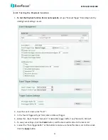
90°
360°
360°


