background image


EZN850 


Installation Guide   


Copyright © EverFocus Electronics Corp, 

Release: Jan. 2009


Summary of Contents for NeVio EZN850

Page 1: ...EZN850 Installation Guide Copyright EverFocus Electronics Corp Release Jan 2009 ...

Page 2: ... Please see 6 Network Connection on page 21 5 Set up IP address and network setting by IP Utility See 7 Assign IP address by Utility on page 23 Package Contents Network camera x1 Printed Installation Guide x1 Software APs including user s manual CD x1 Mounting kit includes Long Screws x 4 for mounting bracket Short Screws x 4 for connecting camera body to bracket Expanding Screws x 4 Hex key x 1 f...

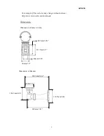
Page 3: ...b site may change without notices http www microsoft com downloads Dimensions Dimension of holes to holes Dimension of Bracket 80mm 3 2 112 7mm 4 5 49mm 1 96 88 5mm 3 54 220 5mm 8 68 84mm 3 31 106 5mm 4 19 112 7mm 4 44 199mm 7 83 ...

Page 4: ...EZN850 4 Dimension of whole camera with bracket 377 3mm 15 09 295mm 11 8 243 5mm 9 74 107 5mm 4 3 ...

Page 5: ...tion 9 3 1 Wiring and Mounting 10 3 2 Adjusting Camera Position 16 3 3 Adjusting Vari focal Lens 17 4 Lens Adjustment 18 4 1 Lens Setting 18 5 OSD Configuration 19 6 Network Connection 21 7 Assign IP address by Utility 23 7 1 Automatically assign an IP 23 7 2 Manually assign an IP address and change network setting 25 ...

Page 6: ...EZN850 6 1 Camera Component Description Bracket Sun shield Fixing screw for sunshield SD card slot Ethernet Power connector Terminal connector Video output Control key selection switch Control key ...

Page 7: ...to control OSD menu by using the control key or switch to LENS to adjust zooming and focus by using the control key please refer to 4 1 Lens setting and 5 OSD Configuration for details 6 Ethernet RJ 45 port Connect to LAN via this standard RJ 45 connector Yellow indicator light On means 100Mbps Off means 10Mbps Green indicator light On means link flicking means active Off means link fail 7 Power I...

Page 8: ...to Alarm In Out device 12VDC Provide power source for IR illuminator Max load is 1A IR illuminator is optional GND Ground pin for illuminator RS485 A half duplex RS 485 interface for keyboard controlling Terminal connector schematic diagram DC OUT ...

Page 9: ...ire and mount the camera See 3 1 Wire and Mounting Adjust the camera position See 3 2 Adjusting camera position Adjust the lens See 3 3 Adjusting lens Warning To prevent electrical shock turn off the electrical power before making electrical connections Do not expose the appliance to water or moisture nor try to operate it in wet areas ...

Page 10: ...le and Alarm RS485 cable through the bracket Note Please use Internet cable without RJ45 connector otherwise you cannot go through cable gland 2 Fix the bracket to wall by using 4 screws LAN cable Power cable LAN cable Power cable Alarm RS485 cable Alarm RS485 cable ...

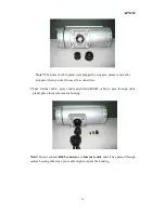
Page 11: ...mera s back cover Loose the 2 screws from the back panel cover then open the back cover 4 Take off the cap of cable gland which is under the camera Screws for back panel Power cable Φ10 3mm LAN cable Φ6mm Alarm RS485 Φ5mm ...

Page 12: ...en you need to use it for connection 5 Take internet cable power cable and Alarm RS485 cable to pass through cable gland place them into camera housing Note Do not connect RJ45 connector to Internet cable until it has passed through camera housing otherwise your cable might not pass the housing ...

Page 13: ...Note 1 Power cable s diameter must be less than 10 mm 2 Alarm RS485 cable must be less than 5 mm 6 Close the waterproof cap and fix cable gland to the base of camera firmly LAN cable Power cable Alarm RS485 cable ...

Page 14: ...e to the proper connector a Connecting LAN Connect internet cable to Ethernet port b Connecting Power 24VAC model connect 24VAC power and GND 100VAC 240VAC model connect PE N and L Note Please do not connect 100VAC 240VAC power to 24VAC model c Insert the SD card if you want to record video in SD card 1 8 T568B 1 White Orange 2 Orange 3 White Green 4 Blue 5 White Blue 6 Green 7 White Brown 8 Brown...

Page 15: ...d Connecting Alarm RS485 optional Connect Alarm cable to Alarm connector and RS485 cable to 485 and 485 Please use screw driver to lose and tight the screw under the connector when you do connection The terminal connector is removable for easier connection 10 Close the back cover and screw the 2 screws firmly Now you are done with the installation Note Before you close the cover please make sure c...

Page 16: ...era Position Adjust camera s angle vertically or horizontally by using hex key included in package Screws for back panel Loose this screw to make angle adjustment vertically Loose this screw to make angle adjustment horizontally ...

Page 17: ...sting Vari focal Lens EZN850 offers a 6 50mm lens that can be motorized controlled Open camera s base a control key is attached at inner side of the base Detach the control key and use this key for OSD or Lens setting UP ...

Page 18: ... Please turn the control key selection switch at the back panel to Lens Use the control key to do lens setting Turn joystick up or down to adjust zoom in zoom out Turn joystick left or right to adjust focus The Cursors mini stick Mini joystick UP ...

Page 19: ...e general OSD menu II Navigate among the OSD Menu Items Turn joystick up or down to move the cursor up or down III Change Modes or Setting Parameters Turn joystick left or right to adjust the mode or parameter of settings IV Switch to Sub menu Screens When the item with sub menu is selected press the mini joystick to switch to the sub menu for further settings Please refer to the diagram below The...

Page 20: ...urn to Previous Page Press the mini joystick to return to previous page VI Close the Host Menu Screen To close the menu screen navigate to the EXIT item and press the mini joystick Sub Menu Main Menu LENS LEVEL 25 SETUP LENS DC SHUTTER ___ WHITE BAL ATW BACKLIGHT OFF AGC MIDDLE DNR LOW SENS UP AUTO SPECIAL EXIT ...

Page 21: ... LAN through a router By doing port forwarding you can view camera outside of internal LAN on internet b Direct High Speed Connection Direct High Speed Connection connect camera directly to modem without a router You need to assign the IP address you obtain from internet service provider to IP camera Encoder To access the camera just type http IP address of your internet provider If you have a dyn...

Page 22: ...EZN850 22 c One to one connection from PC to IP camera You can connect directly without switch However only the PC connecting to camera can view the IP camera ...

Page 23: ...administrators for more detail of network setting reference To make IP camera accessible on the network you need to assign an IP address IP utility in supplied CD is a recommended tool to assign IP address The default network setting is DHCP IP utility offer 2 ways of IP configuration a Automatically detect EverFocus IP Address Please see 7 1 b Assign IP address and change the setting manually Ple...

Page 24: ...dress and DNS2 Address c The IP address of EZN850 will be automatically detected and assigned Select the IP camera you want to see or configure d Click Connect to selected IP You will go into IP camera web browser Then finished Note Default Administrator User ID is user1 and default password is 11111111 You can change it in Setting Menu Please see 4 5 USER of the user s manual ...

Page 25: ...nnect to selected IP after select IP camera click Login You will be asked to enter Administrator s User ID and Password In order to make configuration as highest security level only administrator level is allowed to do network setting Note Default User ID is user1 and default password is 11111111 ...

Page 26: ...wish to make change and enter the desired new value After the change is done press Set Configuration to confirm setting c Click Connect to selected IP and the browser will automatically connect to the EZN850 network page Note Please use Internet Explorer as default Browser ...

Page 27: ...EZN850 27 d When you see the following menu it means you log in successfully Please refer to User s manual for detailed camera setting e Exit Close IP Utility window to finish your setting ...

Page 28: ...081 www everfocus co jp Your EverFocus product is designed and manufactured with high quality materials and components which can be recycled and reused This symbol means that electrical and electronic equipment at their end of life should be disposed of separately from your household waste Please dispose of this equipment at your local community waste collection recycling centre In the European Un...

Reviews: