background image


34 

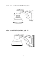
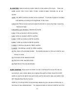
5.  Snap main body to the indoor recessed mount bracket.   


NOTE:   


Aim the Arrow label of the main body to the same Arrow label of the bracket when you 

need to push the main body toward bracket. 


6.  Turn the housing of speed dome until it fixes to the top housing.   


Summary of Contents for Speed Dome EPTZ3100

Page 1: ...Speed Dome EPTZ3100 EPTZ3100I USER MANUAL Date Jan 2009 ...

Page 2: ... 2 3 1 Address Setting 16 2 3 2 Communication Protocol Setting 20 2 3 3 Transmission Speed Setting Baud Rate Setting 20 2 4 Bracket and Speed Dome Installation 21 2 4 1 Installation Requirements 21 2 4 2 EPTZ3100 Dome Camera Wall Mount Simple Installation 22 2 4 3 EPTZ3100 Dome Camera Wall Mount Installation 25 2 4 4 EPTZ3100 Dome Camera Ceiling Mount Installation 32 2 5 Bracket and Adapter 36 2 5...

Page 3: ... BALANCE 42 3 2 5 DAY NIGHT 42 3 2 6 DIG NOISE REDUCE 43 3 2 7 WIDE DYNAMIC RANGE 43 3 2 8 EXIT 44 3 3 POSITIONS 45 3 4 OSD AREAS 48 3 4 1 CAM TITLE 48 3 4 2 AREAS 48 3 4 3 DIRECTIONS 50 3 4 4 DISPLAY 52 3 4 5 EXIT 54 3 5 AUTO MODES 54 3 5 1 AUTOPAN 54 3 5 2 PRESET TOURS 57 3 5 3 PATTERN 58 3 5 4 AUTO RESUME 59 3 5 5 RESUME TO 59 3 5 6 POWER UP FUNC 60 3 5 7 AUTO FLIP 60 ...

Page 4: ...ON DETECT 64 3 6 4 EXIT 64 3 7 PRIVATE ZONES 65 3 8 SYSTEM 67 3 9 INFO 68 3 10 EXIT 69 4 EPTZ3100 3100I FUNCTION SETUP AND OPERATION 70 4 1 Manual Control Mode 70 4 2 Auto Pan Mode 70 4 3 Position Setting 71 4 4 Tour Mode 72 4 5 Alarm Link to a Position Tour 73 4 6 Other Operations 74 ...

Page 5: ... This full functioned speed dome can perform best quality images EPTZ3100 for outdoor model EPTZ3100I for indoor model Built in 30x Optical Zoom Lens Super High Resolution 520TV Lines True Day Night function IR Cut Filter Removable Wide Dynamic Range Digital Slow Shutter Privacy Zone Masking Motion Detection Auto detection of protocols Tilt rotation range 180 192 preset positions are available 16 ...

Page 6: ...trolled by keyboard EKB500 Built in fan to enhance heat dissipation at high temperature and circulate heat to keep system operation at low temperature Built in 4 alarm inputs and 2 alarm outputs All of the features make the intelligent high speed dome camera works for a wide range and demanding application such as banks airports stations casinos streets of cities intelligent buildings etc ...

Page 7: ...s PAL Digital Slow Shutter 128x Shutter Selection AUTO A FLK Manual 128x 1 60 1 50 1 120 000 selectable Lens Type 30x optical zoom f 3 3 mm wide to 99 0mm tele F1 6 to F3 2 Zoom Ratio 240x max 30x Optical and 8x Digital zoom True Day Night Yes Auto DAY NIGHT Backlight Comp Yes OFF LOW MIDDLE HIGH Wide Dynamic Range Yes OFF ON AUTO White Balance Indoor Outdoor MAN5100K MAN3200K MAN2000K ONE PUSH Mo...

Page 8: ...well time at preset position 1 99 available Tour 16 groups Tour point per group 16 preset positions Pattern 4 patterns with 90 sec long each Fan Fan auto starts Position Accuracy 0 1 Alarm 4 in 2 out with tour position auto triggering Built in Menu for Functions Yes Communication RS 485 Communication Speed 1200 2400 4800 9600bps Built in Protocols EVF 1 EVF 2 Pelco P Pelco D A Type Plus D AUTO Pan...

Page 9: ... 1 Profile of EPTZ3100 EPTZ3100I Wall Mount Bracket Sun shield optional Bubble Camera main body Top housing Camera module Outer housing EPTZ3100I Bubble Outer housing Top housing Camera main body Camera Module EPTZ3100 ...

Page 10: ...g to all cables The connectors of cable names are marked on the board in white text The details of the alarm connector are shown on the APPENDIX There are 4 alarm inputs and 2 alarm outputs available represented by Pin 1 12 Pin 13 and 14 are video pins for connecting to video cable Pin15 16 are RS485 pin for connecting to keyboard Pin 17 and 18 are power pin for connecting to 24VAC power EPTZ3100 ...

Page 11: ...Output Normal Close B 4 ALM_NO_A Alarm Output Normal Open A 5 ALM_COM_A Alarm Output Common A 6 ALM_NC_A Alarm Output Normal Close A 7 ALMIN1 Alarm Input 1 8 GND Ground 9 ALMIN2 Alarm Input 2 10 ALMIN3 Alarm Input 3 11 GND Ground 12 ALMIN4 Alarm Input 4 13 VIDEO 14 VIDEO 15 RS485 16 RS485 17 AC24A 18 AC24B ...

Page 12: ...EPTZ3100 EPTZ3100I to a monitor 3 Connect the power to the EPTZ3100 EPTZ3100I and a keyboard EKB500 After the EPTZ3100 EPTZ3100I finishes the self test mode you can start to operate the EPTZ3100 EPTZ3100I via the keyboard To operate the EPTZ3100 EPTZ3100I IRIS Focus F Zoom In N Out UP DOWN LEFT RIGHT ZoomIN ZoomOUT 1 Shift the Joystick up down or right left to view from camera 2 Turn the top of th...

Page 13: ...age The detail accessories are listed below Standard Camera Main Body x 1 Top Housing x1 Outer Housing with Bubble x1 Tool packet Glove x 1 pair RS485 Terminal Block 3 desiccant packs Optional Accessories EPTZ PBOX External Power Connection Box Corner Mount Adapter Pole Mount Adapter Indoor Ceiling Pendent Mount Bracket Outdoor Sunshield Indoor Recessed Mount Bracket Wall Mount Bracket Indoor Conc...

Page 14: ...14 EKB500 Keyboard EKB200 USB Controller Keyboard ...

Page 15: ...00 EPTZ3100I to a DVR or a monitor An amplifier may be needed if the video cable is too long RS485 Cable Yellow wire represents RS485 orange wire represents RS485 Connect RS485 to EKB500 and you will be able to control the speed dome by a keyboard If you are unable to control the speed dome with EKB500 it is probably due to a mis connection Please try to switch RS485 wires and connect again 2 3 In...

Page 16: ...the EPTZ3100 EPTZ3100I should be set to correspond properly with a control device to control multiple dome cameras The address codes are made up by the dip switch on the camera main body The 8 bits dip switch indicates the binary coded of the address and there are 256 addresses can be selected 0 255 It also means that there are up to 256 dome cameras that can cascade on the RS 485 bus The dip swit...

Page 17: ...RS 485 ID address show on the speed dome White part represents the switch key For example for EVF protocol white keys are all switched downward for ID Address 0 white keys are all switched downward ON 1 2 3 4 5 6 7 8 ON 1 2 3 4 5 6 7 8 ID address Protocol Baud rate ...

Page 18: ...ss Switch Address Switch Address Switch Address Switch Address Switch Address ON 1 2 3 4 5 6 7 8 Switch Address 65 ON 1 2 3 4 5 6 7 8 66 ON 1 2 3 4 5 6 7 8 67 ON 1 2 3 4 5 6 7 8 68 ON 1 2 3 4 5 6 7 8 69 ON 1 2 3 4 5 6 7 8 70 ON 1 2 3 4 5 6 7 8 71 ON 1 2 3 4 5 6 7 8 72 ON 1 2 3 4 5 6 7 8 73 ON 1 2 3 4 5 6 7 8 74 ON 1 2 3 4 5 6 7 8 75 ON 1 2 3 4 5 6 7 8 76 ON 1 2 3 4 5 6 7 8 Switch Address 77 ON 1 2...

Page 19: ...191 Switch Address Switch Address Switch Address Switch Address Switch Address Switch Address ON 1 2 3 4 5 6 7 8 Switch Address 193 ON 1 2 3 4 5 6 7 8 194 ON 1 2 3 4 5 6 7 8 195 ON 1 2 3 4 5 6 7 8 196 ON 1 2 3 4 5 6 7 8 197 ON 1 2 3 4 5 6 7 8 198 ON 1 2 3 4 5 6 7 8 199 ON 1 2 3 4 5 6 7 8 200 ON 1 2 3 4 5 6 7 8 201 ON 1 2 3 4 5 6 7 8 202 ON 1 2 3 4 5 6 7 8 203 ON 1 2 3 4 5 6 7 8 204 ON 1 2 3 4 5 6 ...

Page 20: ...d dome EPTZ3100 EPTZ3100I will enter a self test mode 2 3 3 Transmission Speed Setting Baud Rate Setting The 4th and 5th bits on the PCB board are used to set the Baud Rate The default baud rate setting is 9600 Notice Please make sure the power is off before setting and restart the EPTZ3100 EPTZ3100I to enable a new value after changing ON 1 2 3 4 5 6 7 8 SW2 Protocol Baud Rate Terminal Resistance...

Page 21: ...l regulations Service personnel should expect potential problems such as surface strength surface material falling objects outer breaches building vibration or other similar conditions 2 Check for all necessary materials and ensure if the selected installation location is suitable for the EPTZ3100 EPTZ3100I ETPZ3100 overview Bracket base Bracket Top housing Main body ...

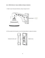
Page 22: ...ome Camera Wall Mount Simple Installation 1 Screw the top housing to bracket by using a hexagon wrench 2 Put the waterproof silicon pad on top of the bracket base for waterproof purpose Waterproof silicon pad Bracket base ...

Page 23: ...as to be connected via a terminal block If you need to connect alarm cable thread the alarm cable through the second hole Note Since video cable and power cable are bare wires installers have to prepare their own BNC connector and power cord connector 4 Screw in 4 screws for mounting the bracket base Video cable Power cable RS485 cable Alarm cable ...

Page 24: ...24 5 Screw in 4 long screws to fix the bracket to bracket base ...

Page 25: ...allation location that is a wall a pole or a ceiling needs to support above five times the total weight of the camera assembly about 16 kg to avoid shaken images and dropping 1 Pull the hole of the base board to open it Detach the power and RS485 wires first by using a screw driver ...

Page 26: ...siccant packs to be applied 3 When all the desiccant packs are pasted and alarm cables are connected properly put the base board back to its original place you will need to pull open the switch in order to have the base board fitted to the top housing Note To close the base board please push the base board twice consequently to lock it up ...

Page 27: ...you thread from the wall or ceiling RS485 cable has to be connected via a terminal block If you need to connect alarm cable thread the alarm cable through the second hole Note Since video cable and power cable are bare wires installers have to prepare their own BNC connector and power cord connector Waterproof silicon pad Base board Video cable Power cable RS485 cable Alarm cable ...

Page 28: ...28 6 Screw in 4 screws for mounting the bracket base 7 Thread the cable through the bracket ...

Page 29: ...29 8 Screw the top housing to bracket by using a hexagon wrench 9 Screw in 4 long screws to fix the bracket to bracket base ...

Page 30: ...ower and RS485 wires back to power pin and RS485 pin If you need to connect alarm connect alarm cable to alarm pin 11 Hold and push the main body toward the bracket until it is firmly fixed to the bracket To release it press orange buttons at both sides of the body ...

Page 31: ... hold the main body carefully otherwise it may fall down Note 2 Aim the Arrow label of the main body to the same Arrow label of the bracket when you need to push the main body toward bracket 12 Twist the cover of main body to top housing clockwise until it is firmly fixed to top housing ...

Page 32: ...00 Note When turning on the power EPTZ3100 will enter self inspection mode and carry out a self testing program After finishing self inspection you can start to operate the EPTZ3100 2 4 4 EPTZ3100 Dome Camera Ceiling Mount Installation Indoor Recessed Mount Bracket Surface Ring The indoor recessed mount bracket and surface ring are used for ceiling mount installation Installation steps are describ...

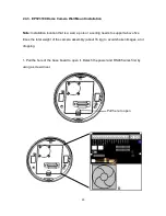
Page 33: ...to the 3 holes of indoor recessed mount bracket 3 Put the indoor recessed mount bracket to the hole that you just made on ceiling 4 Use a screwdriver to turn the rotation clips x 3 until they firmly fix to the ceiling rotation clip rotation clip ...

Page 34: ...indoor recessed mount bracket NOTE Aim the Arrow label of the main body to the same Arrow label of the bracket when you need to push the main body toward bracket 6 Turn the housing of speed dome until it fixes to the top housing ...

Page 35: ...35 7 Aim bracket s fillister to surface ring s fillister turn it until it is firmly fixed ...

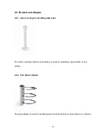
Page 36: ...r Ceiling Pendent Mount Bracket The indoor ceiling pendent mount bracket is used for installing a speed dome on the ceiling 2 5 2 Pole Mount Adapter The pole adapter is used for installing a wall mount bracket to a pole indoors or outdoors ...

Page 37: ...corner mount is used for installing a wall mount bracket to a 270 corner of walls indoors or outdoors 2 5 4 Indoor Concrete Ceiling Mount Adapter Indoor Concrete Ceiling Mount Adapter is used for indoor installation to concrete ceiling ...

Page 38: ...ure of the Setup Menu Press MENU to enter camera setup menu Turn the Joystick up down to change subentries and right left to change the setting If there is an arrow at the end of selection it means that selection has a sub menu please press Enter key of keyboard to enter sub menu diagram 3 1 VIDEO SETTINGS POSITIONS OSD AREAS AUTO MODES ALARM PRIVATE ZONES SYSTEM INFO EXIT ...

Page 39: ...are 4 options in Exposure EL SHUTTER SLOW SHUTTER IRIS MODE and AUTO GAIN CTRL VIDEO SETTINGS POSITIONS OSD AREAS AUTO MODES ALARM PRIVATE ZONES SYSTEM INFO EXIT EL SHUTTER AUTO SLOW SHUTTER AUTO X4 IRIS MODE AUTO AUTO GAIN CTRL MIDDLE EXIT EXPOSURE FOCUS MODE ONE PUSH DIGITAL ZOOM OFF WHITE BALANCE OUTDOOR DAY NIGHT AUTO DIG NOISE REDUCE MIDDLE WIDE DYNAMIC RANGE OFF EXIT EXPOSURE FOCUS MODE ONE ...

Page 40: ...00 1 2500 sec shutter for NTSC and PAL 1 10000 1 10000 sec shutter for NTSC and PAL 1 120000 1 120000 sec shutter for NTSC and PAL X2 Two times of the standard shutter The standard shutter is 1 60 sec for NTSC and 1 50 sec for PAL X4 Four times of the standard shutter X6 Six times of the standard shutter X8 Eight times of the standard shutter SLOW SHUTTER Slow electronic shutter In order to enhanc...

Page 41: ...er a certain level the AGC functions to define whether to control the Gain automatically or not Select one mode from OFF LOW MIDDLE HIGH EXIT Select Exit to save settings and exit from current page 3 2 2 FOCUS MODE In Focus mode we define focus type from ONE PUSH AUTO and Manual ONE PUSH Enable the one push trigger focus mode The focus lens holds the same position until the next trigger command is...

Page 42: ...OR This mode is an automatic mode The camera balances the color automatically depending on the source of the light from 1800 to 10500K It is recommended to use this mode in an area under the limited color temperature ONE PUSH One Push Auto White Balance Mode MAN2000K This mode is a manual mode The color temperature will be fixed at 2000K MAN3200K This mode is a manual mode The color temperature wi...

Page 43: ...s background noise under low light conditions differently in different modes The noise reduction effect grows in OFF LOW MIDDLE and HIGH modes in order OFF No noise reduction effect LOW Noise reduction effect is small but there is little afterimage MIDDLE Noise reduction effect is generally effective in this mode Noise can be reduced properly and the afterimage is not strong HIGH Noise reduction e...

Page 44: ...n the wide dynamic range is ON some part of the image may appear solarized This is normal for the wide dynamic range and is not a camera malfunction 3 2 8 EXIT Select Exit to save settings and exit from current page ...

Page 45: ...6 preset positions can be set in one page Once the preset position is selected there will be a star sign beside preset number then go to RETURN and turn the joystick Left Right to exit from current page diagram 3 5 VIDEO SETTINGS POSITIONS OSD AREAS AUTO MODES ALARM PRIVATE ZONES SYSTEM INFO EXIT SET POSITIONS FREEZE PICTURE OFF EXIT PRESET POSITION 1 2 3 4 5 6 7 8 9 10 11 12 13 14 15 16 17 18 19 ...

Page 46: ... star sign beside position number Clear Select Clear and press Enter key of keyboard and the POSITION will be cleared You will automatically go back to the sub menu of PRESET POSITION Please see diagram 3 7 diagram 3 7 PRESET NO 1 POSITION SET SPEED 100 DWELL TIME S 4 FOCUS MODE MANUAL WHITE BALANCE AUTO TITLE 1 DEFAULT ON RETURN MOVE TO POSITION IRIS SAVE AND RETURN PRESET POSITION 1 2 3 4 5 6 7 ...

Page 47: ...r TITLE Enter title name for the preset position Turn the joystick Up or Down to select the character Turn the joystick Left or Right to select the character position Once the title is inputted turn the joystick to the last character and keep turning right again to return to previous mode DEFAULT Select ON to set the preset position to default value FREEZE PICTURE Speed dome will stop at the previ...

Page 48: ...he joystick Left or Right to select the character position Once the title is inputted turn the joystick to the last character and keep turning right again to return to previous mode 3 4 2 AREAS Press Enter key of keyboard or turn joystick Left Right to enter AREAS sub menu diagram 3 9 VIDEO SETTINGS POSITIONS OSD AREAS AUTO MODES ALARM PRIVATE ZONES SYSTEM INFO EXIT CAM TITLE EPTZ3100__ AREAS DIRE...

Page 49: ...o Range section and press Enter key to enter Range sub menu Use the joystick to move speed dome to its left position Press IRIS key to save left position setting and go to next step or press IRIS to cancel diagram 3 10 Use the joystick to move speed dome to its right position Press IRIS or IRIS key to save and return diagram 3 11 ZONE1 MOVE TO LEFT POSITION IRIS SAVE AND NEXT STEP IRIS CANCEL ZONE...

Page 50: ...NS sub menu see diagram 3 12 diagram 3 12 Press Enter key of keyboard or turn joystick Left Right to enter DIRECTIONS sub menu see diagram 3 13 diagram 3 13 1 Press Enter key of keyboard or turn joystick Left Right to enter Set North position menu 2 Move the joystick to North position DIRECTIONS NORTH SET NORTH DEFAULT NORTH PUSH ENT RETURN CAM TITLE EPTZ3100__ AREAS DIRECTIONS DISPLAY EXIT DIRECT...

Page 51: ...d return diagram 3 14 4 Go to DEFAULT NORTH and press Enter key to set the north position as default north position 5 Go to Return and turn joystick Left Right to return to previous menu DIRECTIONS NORTH SET NORTH DEFAULT NORTH PUSH ENT RETURN ...

Page 52: ...nd Camera Status OFF do not show OSD 2 SEC show OSD for 2 seconds 5 SEC show OSD for 5 seconds 10 SEC show OSD for 10 seconds 2 CAMERA TITLE YES show camera title NO do not show camera title 3 DIRECTIONS YES show directions NO do not show directions SHOW OSD ON CAMERA TITLE NO DIRECTIONS NO ZONES NO PRESET TITLE YES ZOOM NO FAN NO MOTION NO CAMERA STATUS NO RETURN CAM TITLE EPTZ3100__ AREAS DIRECT...

Page 53: ...or zoom out NO do not show zoom multiple 7 FAN YES show fan indication when fan is enabled NO do not show fan indication 8 MOTION YES show motion message when a motion occurs NO do not show motion message when a motion occurs 9 CAMERA STATUS YES shows camera status NO do not show camera status 10 RETURN Turn joystick Left Right to return to previous menu ...

Page 54: ... Left Right to enter AUTOPAN sub menu see diagram 3 17 diagram 3 17 VIDEO SETTINGS POSITIONS OSD AREAS AUTO MODES ALARM PRIVATE ZONES SYSTEM INFO EXIT AUTOPAN PRESET TOURS PATTERN AUTO RESUME OFF RESUME TO POS 1 H POWER UP FUNC PREV MODE AUTO FLIP ON EXIT AUTOPAN ENDLESS MODE ON SPEED 32 DWELL TIME L S 4 DWELL TIME R S 4 SET LEFT POS EMPTY SET RIGHT POS EMPTY DEFAULT ON RETURN AUTOPAN PRESET TOURS...

Page 55: ...255 and 255 is the highest speed c DWELL TIME L S Select dwell time of the left position from 1 99 seconds d DWELL TIME R S Select dwell time of the right position from 1 99 seconds e SET LEFT POS Press Enter key or turn the joystick Left Right to enter SET LEFT POS menu Turn the joystick to the position where you wish to set Left position Press IRIS key of keyboard to save setting and return to p...

Page 56: ...see diagram 3 19 Note When Left Right Position are set the speed dome will patrol from left position to right position clockwise diagram 3 19 MOVE TO POSITION IRIS SAVE AND RETURN AUTOPAN ENDLESS MODE ON SPEED 32 DWELL TIME L S 4 DWELL TIME R S 4 SET LEFT POS SET RIGHT POS DEFAULT ON IRIS RETURN MOVE TO POSITION IRIS SAVE AND RETURN AUTOPAN ENDLESS MODE ON SPEED 32 DWELL TIME L S 4 DWELL TIME R S ...

Page 57: ...s Enter key of keyboard to go next setting Max 16 positions can be set for a tour c DWELL Turn the joystick Up Down to set dwell time of the tour from 1 99 sec or default d SPEED Turn the joystick Right after setting dwell time Turn the joystick Up or Down to select tour speed from 1 255 or default Press Enter key when you finish Tour AUTOPAN PRESET TOURS PATTERN AUTO RESUME OFF RESUME TO POS 1 H ...

Page 58: ... or Down to select pattern number b Turn the joystick Left or Right to select action mode either PLAY SET or CLEAR c Select SET and press Enter key of keyboard diagram 3 22 PATTERN SETUP PATTERN DURATION ACTION PAT1 PLAY PAT2 PLAY PAT3 PLAY PAT4 PLAY RETURN PATTERN SETUP PATTERN DURATION ACTION PAT1 SET PAT2 PLAY PAT3 PLAY PAT4 PLAY IRIS RETURN PATTERN 1 RECORD MODE 90s REMAIN IRIS SAVE AND RETURN...

Page 59: ...o PATTERN SETUP menu diagram 3 23 f RETURN Turn joystick Left Right to return to previous menu 3 5 4 AUTO RESUME Return to previous mode if no action for a period Turn the joystick Left Right to set AUTO RESUME Auto Resume is selectable from OFF After 30 sec After 1 min after 5 min After 10 min After 30 min and After 60 min After this period of time speed dome will resume to the mode you set in RE...

Page 60: ...o Flip function or select OFF to disable Auto Flip 3 5 8 EXIT Exit from the current menu 3 6 ALARM In main menu turn joystick Up or Down to select ALARM Turn joystick Left or Right to enter ALARM sub menu see diagram 3 24 diagram 3 24 3 6 1 ALARM INPUTS Press Enter key of keyboard to enter ALARM INPUTS sub menu see diagram 3 25 VIDEO SETTINGS POSITIONS OSD AREAS AUTO MODES ALARM PRIVATE ZONES SYST...

Page 61: ...ut When there is event triggered the camera will be changed to day mode OFF Disable alarm input diagram 3 25 c REACTION The action will be taken when alarm is triggered OFF No reaction will be taken when alarm is triggered POSITION When the alarm is triggered speed dome will go to the preset position Turn the joystick Left or Right to select on Position and press Enter key to select position numbe...

Page 62: ...om1 16 Press Enter key again to confirm selection d DURATION Duration of alarm input TIMEOUT Turn the joystick Left or Right to select on TIMEOUT and press Enter key to select time out Time out is selectable from 1 99 Press Enter key again to confirm selection LATCHED Turn the joystick Left or Right to select on LATCHED The alarm output will not stop until there is any operation on keyboard TRANSP...

Page 63: ...tput selected Select NO to disable Alarm input 3 e INPUT4 Select YES to enable Alarm input 4 for the alarm output selected Select NO to disable Alarm input 4 f MOTION Select YES to have alarm output triggered when a motion event is detected Select NO to disable this function g SYSTEM ERROR Select YES to have alarm output triggered when system error occurs Select NO to disable this function h REMOT...

Page 64: ...ee diagram 3 27 diagram 3 27 a Turn the joystick Left or Right to select ON for motion detection A window as below pops up diagram 3 28 b SENSITIVITY select motion detection sensitivity level from 1 100 3 6 4 EXIT Exit from the current menu MOTION DETECT 1 OFF SENSITIVITY 50 EXIT MOTION DETECT INFO M1 67 M2 87 ALARM INPUTS ALARM OUTPUTS MOTION DETECT EXIT ...

Page 65: ...nd move to position azimuth of private zone Press IRIS or IRIS key to set private zone size diagram 3 30 VIDEO SETTINGS POSITIONS OSD AREAS AUTO MODES ALARM PRIVATE ZONES SYSTEM INFO EXIT PRIVATE ZONE 1 ON PRIVATE ZONE 1 OFF PRIVATE ZONE 1 OFF PRIVATE ZONE 1 OFF PRIVATE ZONE 1 OFF PRIVATE ZONE 1 OFF PRIVATE ZONE 1 OFF PRIVATE ZONE 1 OFF ZONE COLOR BLACK EXIT PRIVATE ZONE 1 SIZE SET ZONE SIZE IRIS ...

Page 66: ...ate zone position Press IRIS to save and return to previous menu diagram 3 31 d Zone color select private zone area color e Exit exit from current menu PRIVATE ZONE 1 ON PRIVATE ZONE 1 OFF PRIVATE ZONE 1 OFF PRIVATE ZONE 1 OFF PRIVATE ZONE 1 OFF PRIVATE ZONE 1 OFF PRIVATE ZONE 1 OFF PRIVATE ZONE 1 OFF ZONE COLOR BLACK EXIT PRIVATE ZONE 1 SIZE SET ZONE SIZE IRIS JOYSTICK FOR PTZ IRIS SAVE AND RETUR...

Page 67: ...ve done b LANGUAGE Select language The current version only supports English version c PASSWORD Press Enter key or turn joystick Left Right to enter password sub menu diagram 3 33 VIDEO SETTINGS POSITIONS OSD AREAS AUTO MODES ALARM PRIVATE ZONES SYSTEM INFO EXIT AUTO INIT OFF LANGUAGE ENGLISH PASSWORD LOAD DEFAULT PUSH ENT RESTART PUSH ENT EXIT PASSWORD PASSWORD ACTIVE NO ENTER PASSWORD XXXX VERIF...

Page 68: ...revious menu without saving changes d LOAD DEFAULT Press Enter key to load default values all values will return to factory default value e Restart Press Enter key to restart the speed dome f EXIT Exit from current menu 3 9 INFO In main menu turn joystick Up or Down to select INFO Turn joystick Left or Right to enter INFO sub menu see diagram 3 34 diagram 3 34 a VERSION shows firmware version of t...

Page 69: ...t and 1 is counted when the speed dome runs to preset position f X CONT X axis counter This counter counts the x axis movement and 1 is counted when the speed dome pans 360 g Y CONT Y axis counter This counter counts the y axis movement and 1 is counted when the speed dome tilts 180 h Press IRIS key to return to previous menu 3 10 EXIT Exit from the current menu ...

Page 70: ...ng Set Home If you set the time to 0 minute then the camera will go back to home if there is no keyboard operation in 5 seconds This is the minimum no action time for HOME mode Note If HOME function is enabled dome will go to home immediately after powering on 4 2 Auto Pan Mode Two point auto pan Press A Pan to enter the auto pan mode and then the system will ask you to enter the auto pan speed 1 ...

Page 71: ...he position There are up to 192 positions can be preset Three specific preset positions can be set as follows 92 Set Left Limit Stop A position 93 Set Right Limit Stop B position 95 Enter Menu mode Use keyboard control keys to control OSD items Focus F to go downward Focus N to go upward IRIS go to previous setting and IRIS to exit You can directly go to the following specific preset positions 33 ...

Page 72: ...ntrolled by preset position setting Set the parameter of a preset position Press Set Position to set the parameter of a preset position You can set the going to speed 1 239 dwell time 1 239 seconds and the title of the position Shift the joystick Right Left to change bits and shift the Joystick Up Down to change the alphanumeric characteristic The available alphanumeric characteristics are 0 9 A Z...

Page 73: ... Note 1 The difference between the One way tour mode and To and fro tour mode is that the return modes are different For example There is a tour with 3 preset positions 1 2 and 3 The camera runs 1 2 3 1 2 3 in the One way tour mode and 1 2 3 2 1 in the To and fro tour mode Note 2 You could set a pattern tour Press Set Tour and input 0 press Enter Sway the joystick to record the entire tour Press S...

Page 74: ...minated the speed dome will resume action or return to its original position Note 2 After powering on the speed dome it will detect alarm status automatically 4 6 Other Operations The EPTZ3100 EPTZ3100I can work with a DVR that has PTZ control functions and a matching protocol The available control functions depend on different DVRs The EPTZ3100 EPTZ3100I can work with a keyboard that has PTZ cont...

Page 75: ...tion systems for used electrical and electronic product Please help us to conserve the environment we live in Ihr EverFocus Produkt wurde entwickelt und hergestellt mit qualitativ hochwertigen Materialien und Komponenten die recycelt und wieder verwendet werden können Dieses Symbol bedeutet dass elektrische und elektronische Geräte am Ende ihrer Nutzungsdauer vom Hausmüll getrennt entsorgt werden ...

Reviews: