42
Propulsion System
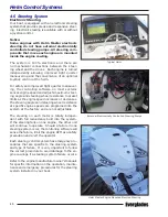
Engine Tilt/Trim Gauges
The tilt/trim gauges monitor the position of each
outboard engine. The upper range of the gauge
indicates the tilt, which is used for trailering and
shallow water operation. The lower range indi-
cates the trim position. This is the range used to
adjust the hull angle while operating your boat on
plane. The Yamaha engine trim indicator is built
into the LCD display. Please refer to the engine
and Command Link Plus
®
owner’s manuals for
more information on the operation of the outboard
power tilt and trim.
Engine Alarms
All outboards are equipped with an audible alarm
system mounted in the helm area that monitors
selected critical engine systems. The alarm will
sound if one of these systems begins to fail. Refer
to the engine owner’s manual for information on
the alarms installed with your engines.
CAUTION
IF THE ENGINE ALARM SOUNDS, IMMEDIATELY SHUT
OFF THE ENGINE UNTIL THE PROBLEM IS FOUND AND
CORRECTED.
Fuel Management
Fuel management systems are standard equip-
ment with some outboard engines. On Yamaha
engines, the fuel management gauge is built into
the Command Link Plus
®
display and can moni-
tor miles per gallon, total gallons used and total
gallons remaining.
Refer to the engine or fuel management manual
for detailed information on that system.
Compass
All boats are equipped with a compass on the top
of the instrument panel. The compass cannot be
adjusted accurately at the factory as it must be
compensated for the influence of the electrical
equipment and electronics unique to your boat.
Therefore, the compass should be adjusted by a
professional after the electronics and additional
electrical accessories are installed and before op-
erating the boat. To adjust the compass for your
area, read the instructions on “Compass Com
-
pensation” given to you in the literature packet.
Instrument Maintenance
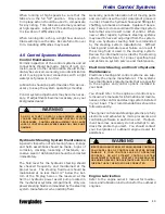
Electrical protection for instruments and ignition
circuitry is provided by a set of fuses or circuit
breakers located on each engine. The ignition
switches should be sprayed periodically with a
contact cleaner/lubricant. The ignition switches
and all instruments, controls, etc. should be pro-
tected from the weather when not in use. Ex-
cessive exposure can lead to gauge and ignition
switch difficulties.
Summary of Contents for 340 DC
Page 1: ...OWNER S MANUAL 340 DC...
Page 2: ...2 Revision 0 11 07 2018...
Page 14: ...14 NOTES...
Page 22: ...22 NOTES...
Page 25: ...25 Operation...
Page 86: ...86 NOTES...
Page 102: ...102 NOTES...
Page 122: ...122 NOTES...
Page 130: ...130 NOTES...
Page 149: ...149 MAINTENANCE LOG Appendix B Hours Date Dealer Service Repairs...
Page 150: ...150 Maintenance Log Hours Date Dealer Service Repairs...
Page 151: ...151 Maintenance Log Hours Date Dealer Service Repairs...
Page 152: ...152 Maintenance Log Hours Date Dealer Service Repairs...
Page 153: ...153 Maintenance Log Hours Date Dealer Service Repairs...
Page 154: ...154 Maintenance Log Hours Date Dealer Service Repairs...
Page 155: ...155 Appendix C BOATING ACCIDENT REPORT...
Page 156: ...156 Boating Accident Report...
Page 157: ...157 Boating Accident Report...
Page 158: ...158 NOTES...
Page 160: ...160 NOTES...
Page 167: ...CAUSE AND SOLUTION...


