59
Electrical System
no loads present on the system. This is normal
as the capacitors in the system drain.
The engine main and auxiliary charging systems
control the charging of the engine and house bat-
teries whenever the engines are operating. The
engine batteries can be temporarily connected in
parallel by the emergency parallel switch in the
helm to provide additional starting current for the
engines. The engine and house batteries are also
charged by the battery charger when plugged into
shore power or when running the generator.
The engine charging systems manage the charg-
ing current for the 12 volt system whenever the
engines are running. The systems automatically
sense the condition of each battery and direct
the available current to the batteries that require
charging. When the engines are started, the engine
alternators start to recharge the batteries. The
charging circuits sense the charge and it is split
between the batteries, with the lowest batteries
receiving the most charge. When the engines are
turned off, charging stops and the sensing circuits
disconnect the batteries from the charging circuits,
thereby automatically isolating the batteries from
one another.
When in port or at anchor, the engine switches
should be off. Only the battery switch that acti
-
vates the House circuit and generator should be
on. This will keep the engine starting batteries in
reserve for starting the engines.
Battery Parallel Switch Operation
A momentary switch in the battery switch panel
that activates the circuit that connects the engine
starting batteries in parallel for extra battery
power while starting the engines. When the switch
is pressed, a relay is engaged that connects the
engine starting batteries, when the switch is re-
leased, the relay is deactivated and the batteries
are isolated.
Notice:
Current is supplied to the automatic switches
for the bilge pumps when the batteries are
connected and the battery switches are off.
Notice:
The manual battery switches completely by-
pass the remote switches at the helm when
they are activated. The circuits cannot be
turned off using the remote battery switches
if the circuits have been activated by the
manual switches.
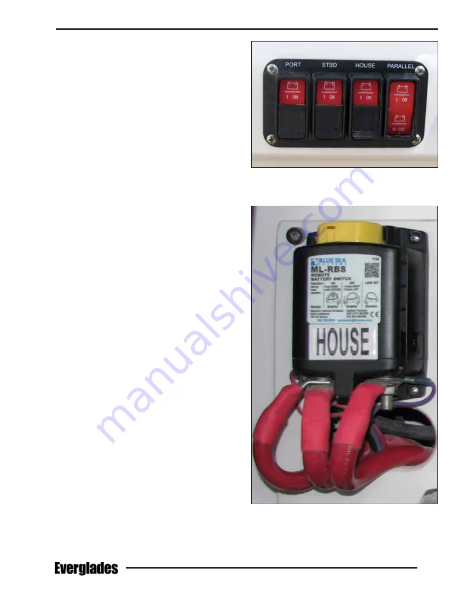
Typical Remote Battery Switch
Remote Battery Switches At Helm
Summary of Contents for 340 DC
Page 1: ...OWNER S MANUAL 340 DC...
Page 2: ...2 Revision 0 11 07 2018...
Page 14: ...14 NOTES...
Page 22: ...22 NOTES...
Page 25: ...25 Operation...
Page 86: ...86 NOTES...
Page 102: ...102 NOTES...
Page 122: ...122 NOTES...
Page 130: ...130 NOTES...
Page 149: ...149 MAINTENANCE LOG Appendix B Hours Date Dealer Service Repairs...
Page 150: ...150 Maintenance Log Hours Date Dealer Service Repairs...
Page 151: ...151 Maintenance Log Hours Date Dealer Service Repairs...
Page 152: ...152 Maintenance Log Hours Date Dealer Service Repairs...
Page 153: ...153 Maintenance Log Hours Date Dealer Service Repairs...
Page 154: ...154 Maintenance Log Hours Date Dealer Service Repairs...
Page 155: ...155 Appendix C BOATING ACCIDENT REPORT...
Page 156: ...156 Boating Accident Report...
Page 157: ...157 Boating Accident Report...
Page 158: ...158 NOTES...
Page 160: ...160 NOTES...
Page 167: ...CAUSE AND SOLUTION...


