78
Electrical System
6.12 Bonding System
& Galvanic Isolator
Your boat is equipped with a bonding system
that interconnects all underwater hardware and
thru-hull fittings to ensure that they are of the
same electrical potential. Sacrificial anodes are
attached to the bonding system at the transom,
the engines and could be installed on the trim tab
planes if your boat is kept in the water. There is
also an anode in the seawater cooling system for
the generator. The anodes deteriorate before the
other metals, thereby protecting the underwater
metals from galvanic corrosion or stray electri-
cal current. Since the anodes are sacrificial, it
is important to monitor them and replace them
when they have deteriorated to 50 - 75% of their
original size. The bonding system is connected to
the DC ground and the earth ground wire for the
AC electrical system. It provides a path for dan-
gerous short circuits in the AC electrical system
to the safety earth ground in the event of a fault
in the shore earth ground connection and when
the boat is away from the dock.
When the boat is connected to shore power at a
marina or city dock, all boats connected to shore
power are connected to a common shore safety
earth ground connection. This circuit provides
essential protection against electrical shock from
faults or short circuits in AC electrical equipment
and, unfortunately, provides a path for low voltage
galvanic current to flow between the bonding sys
-
tem of other boats in the circuit. If one or more of
the boats in the circuit has a stray current electri-
cal problem or is not equipped with proper galvanic
protection, it will seek protection from your boat’s
bonding system through the safety ground circuit.
This could cause accelerated deterioration of the
anodes and/or severe damage to the underwater
hardware. To prevent damage from other boats
in the circuit, a galvanic isolator is installed in
the shore ground circuit that isolates your boat’s
bonding system from the other boats. It prevents
the flow of low voltage galvanic current while still
providing a path for dangerous short circuit cur-
rents in the AC system to the shore safety ground.
6.13 Electrical System Maintenance
DC Electrical System Maintenance
At least once a year, spray all exposed electrical
components behind the helm, in the transom area
and in the plugs with a protector. Removable light
fixture lenses should be removed and wiped clean
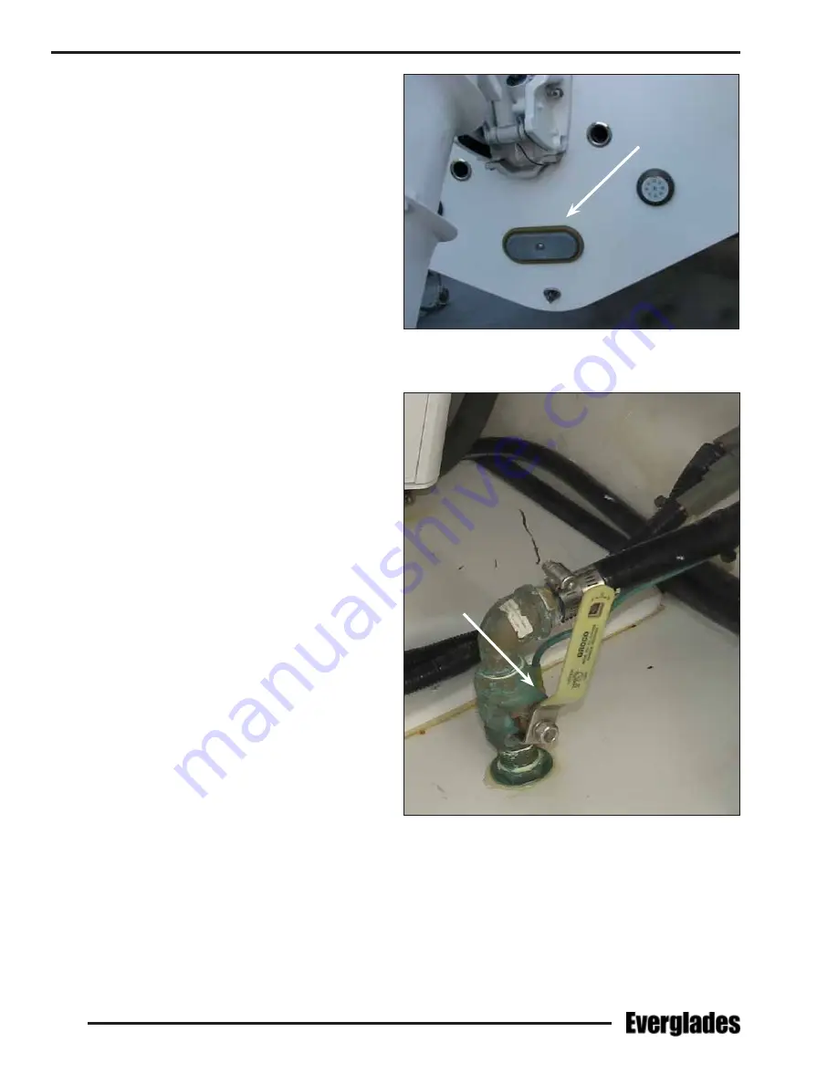
Typical Transom Sacrificial Anode
Typical Seacock Bonding Wire & Connection
with a damp cloth and reinstalled. Some LED light
fixtures are sealed and not serviceable.
Inspect all wiring for proper support and tight
terminals, paying particular attention to portable
cords and plugs.
Summary of Contents for 340 DC
Page 1: ...OWNER S MANUAL 340 DC...
Page 2: ...2 Revision 0 11 07 2018...
Page 14: ...14 NOTES...
Page 22: ...22 NOTES...
Page 25: ...25 Operation...
Page 86: ...86 NOTES...
Page 102: ...102 NOTES...
Page 122: ...122 NOTES...
Page 130: ...130 NOTES...
Page 149: ...149 MAINTENANCE LOG Appendix B Hours Date Dealer Service Repairs...
Page 150: ...150 Maintenance Log Hours Date Dealer Service Repairs...
Page 151: ...151 Maintenance Log Hours Date Dealer Service Repairs...
Page 152: ...152 Maintenance Log Hours Date Dealer Service Repairs...
Page 153: ...153 Maintenance Log Hours Date Dealer Service Repairs...
Page 154: ...154 Maintenance Log Hours Date Dealer Service Repairs...
Page 155: ...155 Appendix C BOATING ACCIDENT REPORT...
Page 156: ...156 Boating Accident Report...
Page 157: ...157 Boating Accident Report...
Page 158: ...158 NOTES...
Page 160: ...160 NOTES...
Page 167: ...CAUSE AND SOLUTION...


