Installation Instructions
1. Before you start installing the solar water heater, please read
carefully all the installation instructions stated and illustrated
in this manual.
2. Before the installation of the solar water heater, it is very
important that the customer and the installer agree on all
the details concerning the correct and safe installation of the
appliance, (such as location, placement point, static resist-
ance and control of the surface on which the appliance will
be placed, piping and wiring run etc).
3. The installation should be done according to the local electric
and plumbing regulations.
4. The location you will choose for the installation of the solar
collector(s) should not be shaded by any obstacles (trees,
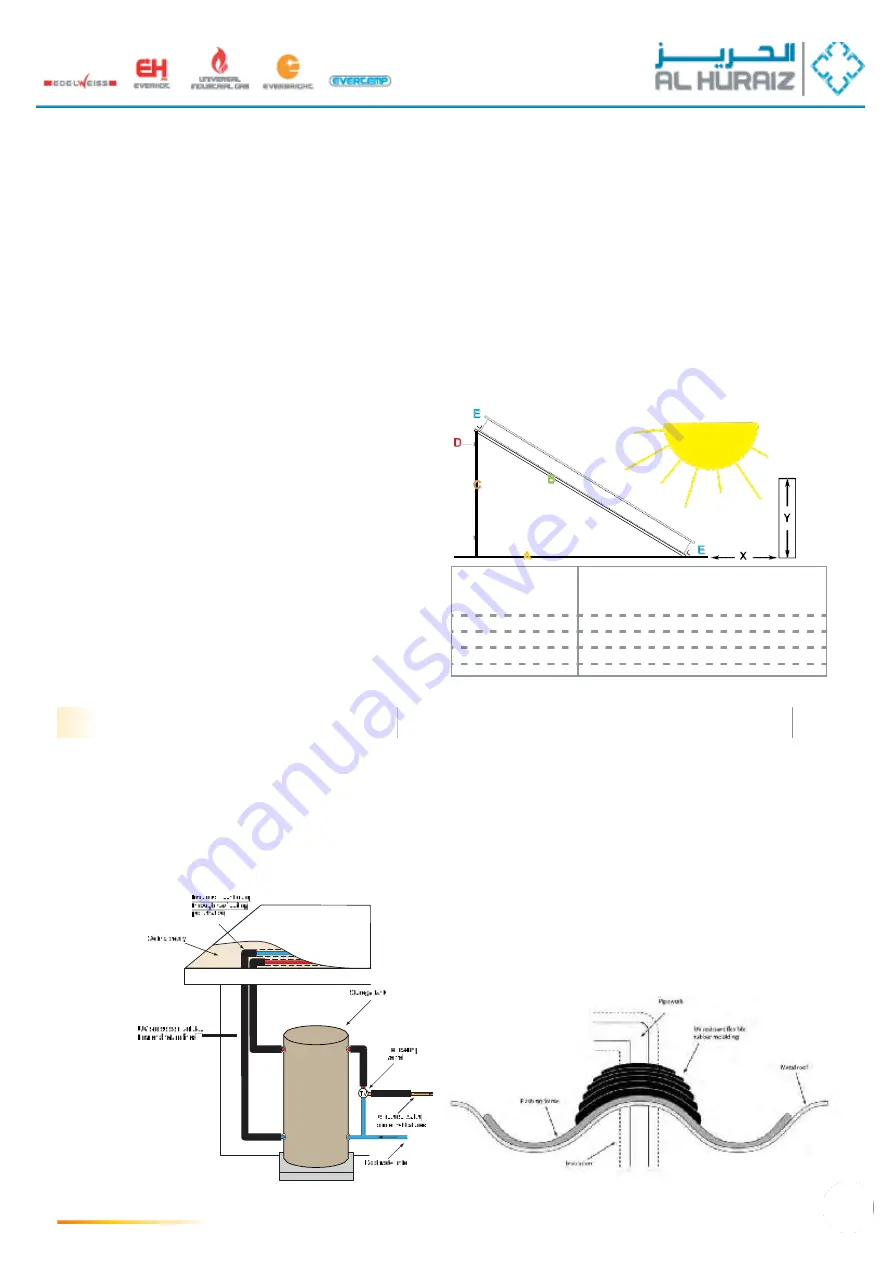
buildings...etc.) all around the year. (see obstacle table here
below).
5. For optimum performance of the solar system, the
collector(s) must face South, for countries located in the
Northern hemisphere and North for countries located in
the Southern hemisphere. In case that it is not totally
possible for the solar collector(s) to face the equator,
you must turn it (them) towards East up to 30º if major
hot water draw is before 14:00 p.m., or towards West
up to 30º if major hot water draw is after 14:00 p.m.
The ideal inclination of the solar collector(s) should be equal
to the latitude in which the installation is done.
6. The support base of the collector(s) is the same for both
flat and inclined roofs. It is diversified only in the way of
it’s assembly (see installation instructions on the following
pages.)
7. If the surface on which the solar collector(s) will be installed
(inclined or flat) is not compatible with the standard equipment
supplied with each appliance, then alternate equipment must
be used. The installer has to choose, propose and install this
alternate equipment, always under the concurrent opinion of
the customer.
8. For installation on an inclined roof, the «D» plates must be
screwed with the appropriate screws and nuts on the roof
timber, in order to secure the right and safe installation of
the collector(s).
9. In regions subject to heavy snowfalls, rainfall, storms, strong
winds, cyclones, tornadoes it is very important to ensure
that the supports of the standard equipment are sufficient to
withstand the weight of the expected snow or the intensity of
the weather conditions. In these cases the collector(s) must
be placed in a stable way on the roof and must be tightened
with additional metal straps.
Continuity in pipe work insulation must be maintained,
although, sometimes, many lengths may need to be joined to
cover the full length of pipe work. In those instances, the join
should be taped and UV-resistant tape used where the join
is made on external pipe work.
Where pipe work penetrates the roof material, the
insulation should go through the penetration with the pipe
work, as shown in figure on the right.
Roof penetrations for pipe work, electrical conduits or
support frames should be sealed with roof lashings to
prevent water leaking into the roof cavity. These lashings are
usually made of EPDM or silicon rubber, with an aluminum
frame that can be mounded to the shape of the roof, as
shown in figure below.
Where possible, penetration should
be done on the high part of the roof profile to avoid the
possibility that water will pool around a penetration that
is located in the valley
of the profile.
Lead lashing should not be used on a roof that is collecting
rainwater for drinking and it must be compatible with other roof
cladding material.
Roof penetration (cross-section)
Insulation continuity
through roof
penetrations
27
Roof flashings
Insulation considerations
latitude
0º- 25º
Distance between
collector and obstacle
X = 1,0 x Y
25º- 35º
X = 1,5 x Y
35º- 45º
X = 2,0 x Y
45º- 50º
X = 2,5 x Y
50º +
X = 3,0 x Y
Summary of Contents for 1000/BL1
Page 1: ......
Page 12: ...CLIMATIC DATA OF SELECTED WORLD CITIES 12...
Page 13: ...Energyoutputofthecollectorinseveralcitiesoftheworld inkWh m2 13...
Page 30: ...Assembly diagram of the support base for one 30...
Page 34: ...Assembly diagram of the support base for three 34...
Page 37: ...Connectionofcollectorsandaccessories 37...
Page 39: ...HYDRAULIC KIT 39...


