background image

SERVICE

MANUAL

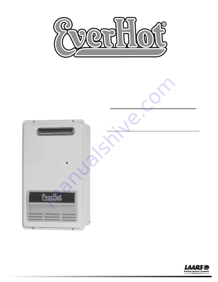
Tankless Gas Water Heater

Troubleshooting Guide

and Instruction for Service

(To be performed ONLY by qualified service providers)

For the LAARS

®

Heating System

EverHot

®  

Exterior Tankless

Gas Water Heater Models:

IGE-199R-10(N,X)

IGE-199C-5(N,X)

Document 11014

Save this manual for future reference


Summary of Contents for IGE-199C-5N

Page 1: ...ing Guide and Instruction for Service To be performed ONLY by qualified service providers For the LAARS Heating System EverHot Exterior Tankless Gas Water Heater Models IGE 199R 10 N X IGE 199C 5 N X...

Page 2: ...power supply to unit when carrying out the following service repairs Read Fault Diagnosis and Wiring Diagram carefully to avoid incorrect wiring Do not disassemble Parts within can not be exchanged or...

Page 3: ...on 17 a Operation Sequence Flow Chart 19 b Sequence Timing Chart 21 VI Troubleshooting error messages 23 a Quick Reference Diagnostic Points 25 b Wiring Diagram 27 c Troubleshooting Flow Chart 29 d Tr...

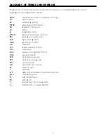
Page 4: ...circuit BTU H British thermal units per hour PSI Pounds per square inch LED light emitting diode GPM gallons per minute mA milliamps W C inches of water column mm millimeters NOx oxides of nitrogen NO...

Page 5: ...able which allows the water heater to be recessed into an outside wall and conceal the piping behind a cover for a more attractive installation The box enclosure dimensions are 40 1 2 H x 14 3 4 W x 9...

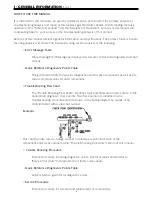
Page 6: ...s Table This guide will identify the specific diagnostic point for each component as well as the correct electrical value for each component Troubleshooting Flow Chart The Trouble Shooting Flow Chart...

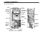
Page 7: ...I GENERAL INFORMATION cont CUT AWAY ILLUSTRATION 7...

Page 8: ...I GENERAL INFORMATION cont SCHEMATIC ILLUSTRATION 8...

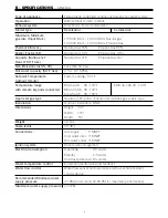
Page 9: ...hout remote Temperature range BC 45 4US 96 120 F MCC 45 4US 96 160 F with remote keypads connected BSC 45 4US 96 120 F MC 45 4US 96 180 F Approved gas type Natural or Propane Ensure unit matches gas s...

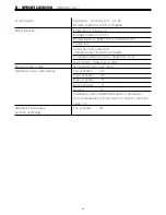
Page 10: ...otection Bimetal sensor anti frost heaters Combustion fan rpm check integrated circuit Over current Glass fuse 3 amp Remote control cable Non polarized two core cable Clearances from combustibles Top...

Page 11: ...199 000 Injector Diameter Upper 045 1 15mm 029 75mm Inches mm Lower 070 1 8mm 045 1 15mm Main Burner B3A7 1 Lean and Rich Bunsen Burner Main Damper H73 115 Upper 6 Lower Not Used Gas Pressure Supply...

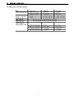
Page 12: ...NTIAL UNITS Natural Gas Model Propane Gas Models Dip Switch Settings Dip Switch Settings SW1 SW2 SW1 SW2 1 Off 1 On 1 Off 1 Off 2 On 2 Off 2 On 2 Off 3 Off 3 Off 3 Off 3 Off 4 Off 4 Off 4 Off 4 Off 5...

Page 13: ...secured by an aluminized steel framework An aluminum manifold with 32 integral injectors supplies gas to the burners and is attached to the front lower cover of the burner box and gas control assembl...

Page 14: ...water 1 Water Flow Sensor and Water Flow Control device Water flow is detected by a turbine magnetic pulse generating device Water flows through the turbine magnetic sensor providing information to t...

Page 15: ...rature outside the heat exchanger reaches 264 F If the thermal fuse melts it breaks an electronic circuit which in turn shuts off the power supply to the gas solenoids deactivating the unit Combustion...

Page 16: ...monitored by the water temperature thermistor located near the outlet of the appliance If the outgoing water temperature reaches 5 F above the preset temperature the burner will automatically deactiv...

Page 17: ...olve The revolution speed is proportional to the water flow A sensor located inside the device relays information in the form of magnetic pulses to the main PCB to determine whether or not water is fl...

Page 18: ...the PCB that there is no water flowing in turn the PCB closes the gas valves The combustion fan continues to operate for 65 seconds This will provide quicker ignition when the tap is turned on and off...

Page 19: ...V SEQUENCE OF OPERATION cont OPERATION SEQUENCE FLOW CHART 19...

Page 20: ...20 V SEQUENCE OF OPERATION cont OPERATION SEQUENCE FLOW CHART...

Page 21: ...V SEQUENCE OF OPERATION cont SEQUENCE TIMING CHART 21...

Page 22: ...22 V SEQUENCE OF OPERATION cont SEQUENCE TIMING CHART...

Page 23: ...properly grounded Check gas solenoid valves for open or short circuits Check power supply for loose connections Check power supply for proper voltage and voltage drops Disconnect all MSA controls Disc...

Page 24: ...oid Valve Circuit Faulty connections Check resistance on each solenoid 72 Flame Sensing Device Faulty Check micro amps produced by flame rod Remove flame rod and check for carbon build up clean with s...

Page 25: ...VDC 1 8K 2K ohms E2 2 3 SV2 Black Blue 80 100 VDC 1 8K 2K ohms E3 2 4 SV3 Black Brown 80 100 VDC 1 8K 2K ohms E4 2 5 POV Pink Pink 2 15 VDC 67 81 ohms C2 3 4 M Water Flow Control Device Servo or Geare...

Page 26: ...ples of temperatures and resistance reading at those temperatures Example 59 F 11 4 14K 86 F 6 4 7 8K 113 F 3 6 4 5K 140 F 2 2 2 7K 221 F 0 6 0 8K Outgoing Water Thermistor White White N A See example...

Page 27: ...a resistance reading of 81 86 ohms and the one located in the water flow sensor valve has a resistance reading of 16 19 ohms Voltage throughout this circuit should be 120 VAC Fuses This unit has 2 in...

Page 28: ...VI TROUBLE SHOOTING cont WIRING SCHEMATIC 28...

Page 29: ...Check for short circuits 1 Measure resistance of each solenoid valve Remove connector E from the PCB before measuring Pink Black SV0 1 7 2 1K Yellow Black SV1 1 7 2 1K Brown Black SV2 1 7 2 1K See pag...

Page 30: ...de 72 displayed on the digital monitor 2 Check flame rod Measure resistance between flame rod terminal C1 and earth See page 36 Resistance 1M Yes No Replace PCB Replace flame rod IGE 2 Error code 32 d...

Page 31: ...nect connector E from the PCB Measure resistance between yellow black of SV1 2 Measure voltage between yellow black of SV1 connector See page 38 1 7 2 1K 80 100 VDC Yes No Yes No Go to B 7 2 Replace g...

Page 32: ...angeover solenoid valve SV3 1 Disconnect connector E from PCB and measure the resistance between brown black See page 39 2 Measure the voltage between brown black wire of the changeover solenoid valve...

Page 33: ...2 Read resistance of the heating element that is mounted on the front of the heat exchanger white wires See page 43 3 Read resistance of heating elements on the heat exchanger outlet hot water line S...

Page 34: ...3 amp glass fuse If the fuse blows again investigate cause of short circuit Check the transformer a Measure the voltage and or resistance at connector F black white wires Normal 100 120 VAC 51 63 res...

Page 35: ...before replacing the remote control Faulty Replace PCB Service Procedure IGE 2 page 47 Check the water flow sensor a Check the voltage at PCB connector B4 red and black wires Normal 11 13 VDC or 5 8 6...

Page 36: ...ocedure IGE 2 page 47 Faulty Replace the flame rod See page 40 for additional information and resistance values pertaining to the flame rod If error 32 is displayed check the water temperature thermis...

Page 37: ...CARRYING OUT CHECKS MARKED WITH A SIGN DISCONNECT THE POWER SUPPLY Motor check If error 61 is displayed check the combustion fan a Measure voltage at connector A1 Black and red wires Normal 6 45 VDC F...

Page 38: ...Procedure IGE 9 page 50 b Measure voltage at the change over solenoid SV1 yellow black wires Normal 80 100 VDC If normal check 8 below Faulty Replace PCB unit Service Procedure IGE 2 page 47 If error...

Page 39: ...d terminals Normal 1 7 2 1 K If normal check b below Faulty Replace the manifold assembly Service Procedure IGE 8 page 49 b Measure the voltage at the changeover solenoid SV3 brown black wires Normal...

Page 40: ...e to the proper gas pressure for gas type being used Faulty Ensure unit is properly grounded Check ground circuit outside home at service pole There should be an eight foot ground rod driven in the ea...

Page 41: ...tem 2 below Faulty Replace the water temperature thermistor Service Procedure IGE 6 page 48 a Disconnect the changeover solenoid SV1 connector and measure resistance at the solenoid terminals Normal 1...

Page 42: ...o and sensor Service Procedure IGE 2 page 47 b Disconnect connector B2 and measure the voltage on the PCB unit side were the orange and or grey or black wires connect to the board Normal 3 3 4 5 VDC I...

Page 43: ...location of this element These are white wires Normal 100 110 If normal proceed to check item 2 below Faulty Replace defective anti frost heater assembly c Check resistance of the two heat exchanger...

Page 44: ...See figure 1 for location of the regulator adjustment screw Below are the proper pressures for Low fire per gas type Propane 0 88 w c 10 w c supply Low fire rate of 15 000 BTU s Natural 0 56 w c 6 w c...

Page 45: ...install the front cover and place the unit back into operation 10 Verify the proper water temperature as set on the controller at your outlets If controllers are not being used the output temperature...

Page 46: ...1 Removal of the Front Panel 47 IGE 2 Removal of the PC Board 47 IGE 3 Removal of the Water Flow Control and Sensor 47 IGE 4 Removal of the Ignition Module 48 IGE 5 Removal of the Combustion Fan 48 I...

Page 47: ...panel in place with a Phillips driver IGE 2 Removal of PC board CAUTION 120 volt potential exposure Isolate the appliance and reconfirm power has been disconnected using a multimeter a Remove the two...

Page 48: ...Phillips screw that secures the sparker module to the unit casing b Disconnect high tension lead and connector IGE 5 Removal of the Combustion Fan CAUTION 120 volt potential exposure Isolate the appl...

Page 49: ...r has been disconnected using a multimeter a To remove the burner manifold remove 6 Phillip screws around the burner plate as shown in the upper right picture b Remove the 3 Phillip screws at the gas...

Page 50: ...h the proper wire colors Pull gas valve assembly out of unit IGE 10 Removal of Heat Exchanger CAUTION 120 volt potential exposure Isolate the appliance and reconfirm power has been disconnected using...

Page 51: ...r if the thermo fuse on the rear of the heat exchanger is blown Service Procedure IGE 10 page 50 a The unit has four thermal fuses see picture below for location b Disconnect and remove the thermal fu...

Page 52: ...r to the water heater 2 Close valves in the cold water inlet and outlet supply 3 Connect PVC hoses may use garden hose to the drain valve outlet fittings Connect a circulator pump to the hose connecte...

Page 53: ...X PARTS BREAKDOWN DISASSEMBLED VIEW CABINET 53...

Page 54: ...X PARTS BREAKDOWN DISASSEMBLED VIEW INTERNALS 54...

Page 55: ...X PARTS BREAKDOWN DISASSEMBLED VIEW INTERNALS 55...

Page 56: ...X PARTS BREAKDOWN DISASSEMBLED VIEW ELECTRICAL 56...

Page 57: ...on Chamber Front Plate 1 116 Spark Ignition Electrode 1 117 Flame Sense Rod 1 118 Electrode Gasket 1 119 Electrode Holder 1 120 Upper Combustion Chamber Gasket 1 122 Combustion Blower Assembly 1 123 B...

Page 58: ...33 120V Anti Frost Heater Assembly 1 734 Sensor Harness 2 1 800 Screw 8 801 Screw 4 802 Washer 4 803 Screw 3 804 Screw 1 805 Screw 3 806 Screw 4 807 Washer 4 808 Screw 4 809 Screw 4 810 O Ring 3 813 O...

Page 59: ...59 Notes...

Page 60: ...vice Service Advisors 20 Industrial Way Rochester NH 03867 603 335 6300 Fax 603 335 3355 1869 Sismet Road Mississauga Ontario Canada L4W 1W8 905 238 0100 Fax 905 366 0130 www Laars com Litho in U S A...

Reviews: