6
I - GENERAL INFORMATION
(cont.)
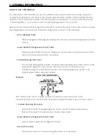
HOW TO USE THIS MANUAL
It is intended for this manual to be used by qualified service personnel for the primary purpose of
troubleshooting analysis and repair of this tankless gas fired water heater. Understanding the basic
operation of the "Main Components" and the "Sequence of Operation" sections of this manual will
contribute greatly to your success in the troubleshooting analysis of this product.
Sections of this manual reference general information and specifications. The primary focus is trouble
shooting analysis and repair. The trouble shooting section consists of the following:
•
Error Message Table
Table showing Error Message as displayed on remote control indicating likely fault and
remedy.
•
Quick Reference Diagnostics Points Table
This guide will identify the specific diagnostic point for each component as well as the
correct electrical value for each component.
•
Troubleshooting Flow Chart
The "Trouble Shooting Flow Chart" identifies fault potentials and directs service to the
appropriate diagnostic check points. The check points are identified in the
troubleshooting procedure and are shown on the wiring diagram by means of an
encircled letter with a subscript number.
Example:
This chart will also refer to a page number to reference a pictorial version of the
component analysis as outlined in the "Trouble Shooting Procedure" section of this manual.
•
Trouble Shooting Procedure
Pictorial procedure including diagnostic points, electrical values and referral to
"Service Procedure" for replacement of faulty components.
•
Quick Reference Diagnostics Points Table
Quick reference guide for all diagnostic points.
•
Service Procedure
Pictorial procedure for removal and replacement of components.
Summary of Contents for IGE-199C-5N
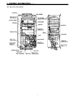
Page 7: ...I GENERAL INFORMATION cont CUT AWAY ILLUSTRATION 7...
Page 8: ...I GENERAL INFORMATION cont SCHEMATIC ILLUSTRATION 8...
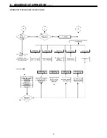
Page 19: ...V SEQUENCE OF OPERATION cont OPERATION SEQUENCE FLOW CHART 19...
Page 20: ...20 V SEQUENCE OF OPERATION cont OPERATION SEQUENCE FLOW CHART...
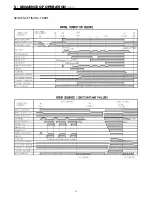
Page 21: ...V SEQUENCE OF OPERATION cont SEQUENCE TIMING CHART 21...
Page 22: ...22 V SEQUENCE OF OPERATION cont SEQUENCE TIMING CHART...
Page 28: ...VI TROUBLE SHOOTING cont WIRING SCHEMATIC 28...
Page 53: ...X PARTS BREAKDOWN DISASSEMBLED VIEW CABINET 53...
Page 54: ...X PARTS BREAKDOWN DISASSEMBLED VIEW INTERNALS 54...
Page 55: ...X PARTS BREAKDOWN DISASSEMBLED VIEW INTERNALS 55...
Page 56: ...X PARTS BREAKDOWN DISASSEMBLED VIEW ELECTRICAL 56...
Page 59: ...59 Notes...

