31
Part
Description
Qty
Part
Description
Qty
101
Computer
1
503 Transportation Wheel
2
102
Console Housing - Upper
1
504 Fold Holder
1
103
Console Housing - Bottom
1
505 Fold Holder Wheel
1
104
Water Bottle Holder
2
506 10mm Foot Cushion
4
105
Safety Key Base
1
507 Upright Cover - LL
1
106
Safety Key
1
508 Upright Cover - LR
1
509 Upright Cover - RL
1
201
Handle Bar
1
510 Upright Cover - RR
1
202
Upright - Left
1
203
Upright - Right
1
601 Running Belt
1
204
Hand Pulse Sensor
2
602 Side Rail
2
205
Power Switch Plate
1
603 End Cap - Left
1
206
Power Switch
1
604 End Cap - Right
1
207
Power Breaker
1
605 Running Deck
1
208
Electric Outlet
1
606 Cushion Pad
8
209
Hand Pulse Sensor Cover - Upper
2
210
Hand Pulse Sensor Cover - Bottom
2
701 ø4x15mm Screw
40
211
Power Switch Plate Base
1
702 Rail Guide
8
212
5 Pin Wire 2500mm
1
703 M8x10mm Bolt
2
213
2 Pin Wire 1900mm
1
704 M8x18mm Bolt
2
214
Handle Bar Cover - Left 1
1
705 M8x42mm Bolt
4
215
Handle Bar Cover - Left 2
1
706 ø4x19mm Screw
2
216
Handle Bar Cover - Right 1
1
707 M8x39mm Bolt
2
217
Handle Bar Cover - Right 2
1
708 M12x85mm Bolt
2
216
Handle Bar Cover - Right 1
1
709 M4x12mm Screw
3
217
Handle Bar Cover - Right 2
1
710 M10x59mm Bolt
2
711 M6x45mm Bolt
3
301
Main Frame
1
712 ø4x19mm Screw
16
302
Front Roller
1
713 M8x25mm Bolt
8
303
Front Roller Shaft
1
714 M5x14mm Bolt
4
304
Rear Roller
1
715 M8x47mm Bolt
1
305
Rear Roller Shaft
1
716 Motor Bolt
1
306
Control Board
1
717 Motor Cushion
1
307
Rear Foot Frame
1
718 Washer
2
308
Rear Foot Frame End Cap
4
719 M10x116mm Bolt
1
309
ø22 x ø10 End Cap
2
720 M8x12mm Bolt
2
721 ø8 Washer
13
401
Motor
1
722 ø10 Washer
3
402
Motor Holder
1
723 M10 Nut
3
403
Belt
1
724 M8 Nut
4
404
Motor Hood - Upper
1
725 M8x35mm Bolt
1
405
Motor Hood - Bottom
4
726 M8x50mm Bolt
1
727 ø3.5x15mm Screw
9
501
Base Frame
1
728 M8x45mm Bolt
2
502
Transportation Wheel Cover
2
Exploded Diagram Parts List
Summary of Contents for EV7000
Page 6: ...6...
Page 11: ...11 Assembly Instructions Insert bottle holders 103 into the computer housing Step 5...
Page 12: ...ON OFF SWITCH 12 Assembly Instructions Connecting to mains Step 6...
Page 24: ...24 Exploded Parts Diagram Console...
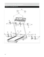
Page 25: ...25 Exploded Parts Diagram Upright Frame and Handle Bar...
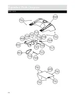
Page 26: ...26 Exploded Parts Diagram Motor Cover...
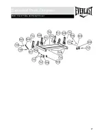
Page 27: ...27 Exploded Parts Diagram Motor Cover Frame and Upright Cover...
Page 28: ...28 Exploded Parts Diagram Walking Belt...
Page 29: ...29 Exploded Parts Diagram Main Frame...
Page 30: ...30 Exploded Parts Diagram Upright Cover and Handle Bar Cover...
Page 32: ...AN AUTHORISED LICENCEE OF EVERLAST WORLD WIDE INC FCSI LTD CUSTOMER HELPLINE 0845 6000 464...


