background image

18

ENGLISH

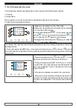
When a phase is over the control panel automatically switches to the next step. 

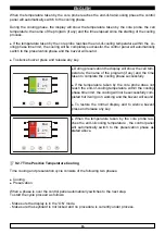
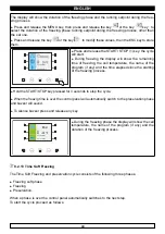
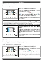
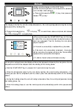
To start the cycle proceed as follows:

► 

 Make sure the display is in the “ON” mode. 

Make sure the keyboard is not locked and no procedu-

re is currently under process. 

► 

Press and release the key 

 (1), press and rele-

ase the key 

 (2), than press and release the key 


(3): in order the displaymodo che sul display compaia il 
simbolo 

The display will show the duration of the cooling phase and the running temperature during the cooling 

process. 

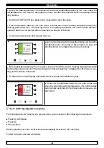
► 

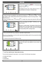
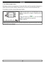
Press and release the MENU key, then press and release the key    

 or the key 

 to select the 

duration of the cooling phase and the running temperature during the cooling process, other than 

the set one. 

 Press and release the key 

 or the key 

 to modify these values then press the ESC key to 

store them. 

Program: MANUAL

Elapsed time: 0 min

► 

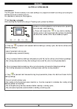
Press and release the START / STOP key (1) : the 

cycle will start. 

 During the hard cooling phase, the display will show 

the remaining time of the cooling phase, the cell tem-

perature, the name of the program (if any) and the time 

elapsed since the starting of the cooling process.

► 

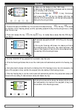
Hold the START/STOP key pressed for 3 seconds to 

stop the cycle. 

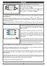
► 

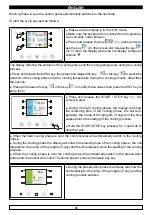
When the hard cooling phase is over the control panel will automatically switch to the cooling 

phase. 

 During the cooling phase the display will show the remaining time of the cooling phase , the cell 

temperture, the name of the program (if any) and the time elapsed since the starting of the cooling 

process. 

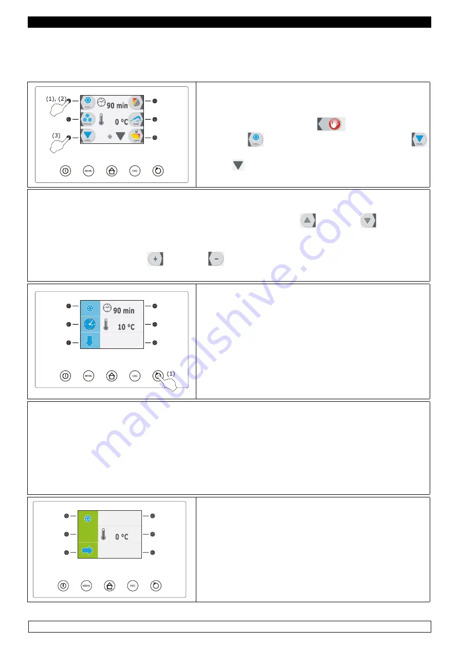
 When the cooling phase is over the control panel will automatically switch to the preservation 

phase and the buzzer will sound. To silence buzzer press and release any key. 

Program: MANUAL

Cycle time: 90 min

End

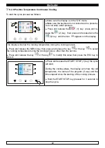
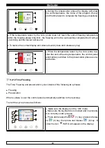
► 

During the preservation phase the display will show the 

cell temperture, the name of the program (if any) and the 

cooling process duration. 

Summary of Contents for KING TROLLEY 120 L

Page 1: ...BLAST CHILLERS SHOCK FREEZERS KING TROLLEY Use and maintenance manual Rev 7 7 ...

Page 2: ... 60 Kg 85 Kg KING TROLLEY 40 L P 150 Kg 220 Kg 120 Kg 170 Kg KING TROLLEY 80 L P 340 Kg 420 Kg 280 Kg 330 Kg KING TROLLEY 120 L P 420 Kg 630 Kg 330 Kg 480 Kg N B the times and quantities in kg above are valid for products with a maximum thickness of 4 cm Maximum time Positive chilling 90 min Freezing 240 min TheblastchillercomplieswiththeEuropeandirectivesasdescribedindetailintheAnnex ECDeclaratio...

Page 3: ...clusively contact a qualified technician The blast chiller is composed of a modular monocoque coated with different materials and insulated with polyurethane foam of density 42 kg m3 In the design and construction all measures have been adopted to ensure a blast chiller that complies with safety and hygiene requirements such as rounded interior corners deep drawing with drain on the outside for th...

Page 4: ... soap or with a cloth or sponge with suitable products disinfection avoid substances that can alter the organoleptic characteristics of the food rinsing cloth or sponge soaked in warm water DO NOT USE WATER JETS frequency weekly is recommended the user can set different frequencies depending on the type of food being stored REMARK Clean frequently the door seals Some preserved products could relea...

Page 5: ...partly open to prevent air stagnation and residual humidity CHAPTER 4 PREVENTIVE MAINTENANCE 4 1 Restarting after a long period of inactivity Restarting after long inactivity is an event that requires preventive maintenance It is necessary to perform a thorough cleaning as described in chapter 2 4 2 Control of the warning and control devices We recommend that you contact your dealer for a service ...

Page 6: ...efrost heater fault contact technical support defrost probe P2 damaged contact technical support accumulation of water or ice in the drip tray drain clogged clean the pipette and the drain blast chiller is not level check levelling CHAPTER 7 INSTRUCTIONS FOR REQUESTING ASSISTANCE Foranytechnicalproblem andanyrequestsforassistanceorservice youmustexclusivelycontact your own dealer with the code and...

Page 7: ...ower supply before working on the unit remove the label of the remote motocondensing unit which warns the user to turn off the power supply before working on the unit to remove the labels applied on the blast chiller indicating grounding to remove the labels applied on the remote motocondensing unit indicating grounding to remove the label applied on the power cord indicating the type of power sup...

Page 8: ...ce the trays too far away from the evaporator NO OK Do not concentrate the trays in one area of the blast chiller in case the load is not complete distribute its height evenly NO OK In case of interruption or failure of the power supply circuit prevent the opening of the doors in order to maintain a uniform temperature inside the blast chiller If the problem persists longer than a few hours it is ...

Page 9: ...ntrol buttons with which the blast chiller is equipped are 1 On off push button ON OFF 2 Option push button MENÙ push button 3 Preset push button HOME push button 4 Cancel push button ESC push button 5 START STOP push button START STOP push button 6 Interactive push button 7 Display 8 Interactive push button ...

Page 10: ... seconds then it will show the OFF mode With card in OFF mode Press and release the ON STAND BY key 1 Should the power supply failure cause the clock error code rtc you need to set date and time again see paragraph 9 2 2 Internal clock setting set date and present time Control panel switching On Off Proceed as follows Make sure the keyboard is not locked and no procedure is currently under process...

Page 11: ...er pro cess the remaining time of cooling and freezing process the cell temperature the name of the program if any and the time elapsed since the starting of the cooling or freezing pro cess 9 2 2 Internal Clock setting Set date and present time fig 3 First set the internal clock at present time proceeding as follows OPTIONS 22 12 08 18 15 HACCP ALARMS PARAMETERS LANGUAGE INTERNAL VALUES LIST ALAR...

Page 12: ... from the above procedure or do not work for 60 seconds 9 2 3 Language setting fig 3 Proceed as follows OPTIONS 22 12 08 18 15 HACCP ALARMS PARAMETERS LANGUAGE INTERNAL VALUES ALARMS LIST Make sure the control panel is switched in the ON mode Make sure the keyboard is not locked and no procedure is currently under process Press and release the HOME key 1 Press and release the MENU key 2 Press and ...

Page 13: ...ling process before each and every operating cycle see paragraph 9 2 15 Precooling The temperature operating cycles are preceeded by a test to verify if the core probe has been inser ted properly see paragraph 9 2 16 Test for checking the core probe proper insertion At the end of every operating cycle the system will automatically switch to the preservation phase except for the continuous cooling ...

Page 14: ...y or the key to change these values then press the ESC key to store them Program MANUAL Elapsed time 0 min Press and release the START STOP key 1 the test to verify if the core probe has been inserted properly will start see paragraph Test for checking the core probe proper insertion If the test is completely successful the cycle starts The count of the cooling maximum duration will start only if ...

Page 15: ...ature the name of the program if any and the time taken to complete the cooling phase suc cessfully If the temperature taken by the core probe does not reach the end of cooling temperature within the cooling phase time limit the cooling process will not be successfully completed but it will go on working and the buzzer will sound To restore the normal display and to silence buzzer press and releas...

Page 16: ...end of cooling temperature and the operating value during the cooling phase other than the set ones Press and release the key or the key to change these values then press the ESC key to store them Program MANUAL Elapsed time 0 min Press and release the START STOP key 1 the test to verify if the core probe has been inserted properly will start see paragraph Test for checking the core probe proper i...

Page 17: ...me of the program if any and the time taken to complete the cooling phase successfully If the temperature taken by the core probe does not reach the end of cooling temperature within the cooling phase time limit the cooling will not be successfully com pleted but it will go on working and the buzzer will sound To restore the normal display and to silence buzzer press and release any key Program MA...

Page 18: ...uring the cooling phase the display will show the re maining time of the cooling phase the cell temperature the name of the program if any and the time elapsed since the starting of the cooling process Hold the START STOP key pressed for 3 seconds to stop the cycle When the cooling phase is over the control panel will automatically switch to the preservation phase and the buzzer will sound To sile...

Page 19: ...gram MANUAL Elapsed time 0 min Press and release the START STOP key 1 the cycle will start During the hard cooling phase the display will show the remaining time of the cooling phase the cell tem perature the name of the program if any and the time elapsed since the starting of the cooling process Hold the START STOP key pressed for 3 seconds to stop the cycle When the hard cooling phase is over t...

Page 20: ... during the cooling process Press and release the MENU key then press and release the key or the key to select the running temperature during the cooling process other than the set one Press and release the key or the key to modify this value then press the ESC key to store it Program MANUAL Elapsed time 0 min Press and release the START STOP 1 key the cycle will start During the cooling phase the...

Page 21: ...ll show the end of freezing temperature and the running temperature during the freezing process Press and release the MENU key then press and release the key or the key to select the end of freezing temperature and the operating setpoint during the freezing process other than the set ones Program MANUAL Elapsed time 0 min Press and release the key or the key to mo dify these values then the ESC ke...

Page 22: ...ature the name of the program if any and the time taken to complete freezing successfully If the temperature taken by the core probe does not reach the end of freezing temperature within the freezing phase time limit the freezing will not be successfully completed but it will go on wor king and the buzzer will sound To restore the normal display and silence buzzer press and release any key Program...

Page 23: ... starts If the test is not successfully completed the buzzer will sound for 5 seconds every 60 seconds and a time cycle will start see paragraph Time soft freezing and preservation During the freezing soft phase the display will show the temperature taken by the core probe the cell tem perature the name of the program if any and the time elapsed since the starting of the freezing process Hold the ...

Page 24: ...ny key Program MANUAL Cycle time 250 min End When the temperature taken by the core probe rea ches the end of freezing temperature the control panel automaticaly switches to the preservation phase as sta ted before 9 2 12 Time Freezing The Time Freezing and preservation cycle consists of the following two phases Freezing Preservation When a phase is over the control panel automatically switches to...

Page 25: ...erature the name of the program if any and the time elapsed since the starting of the freezing process Hold the START STOP key pressed for 3 seconds to stop the cycle When the freezig time is over the control panel will automatically switch to the preservation phase and buzzer will sound To silence buzzer press and release any key Program MANUAL Cycle time 240 min End During the freezing phase the...

Page 26: ...ing soft phase the display will show the remaining time of freezing the cell temperature the name of the program if any and the time elapsed since the starting of the freezing process Hold the START STOP key pressed for 3 seconds to stop the cycle When the freezing soft phase time is over the control panel will automatically switch to the freezing pha se During freezing the display will show the r...

Page 27: ...ey or the key to modify this value then the ESC key to save it Program MANUAL Elapsed time 0 min INF Press and release the START STOP key 1 the cycle will start During the freezing process the display will show the cell temperature the name of the program if any and the time elapsed since the starting of the freezing pro cess Hold the START STOP key pressed for 3 seconds to stop the cycle 9 2 15 P...

Page 28: ... the door is closed i e micro input port is not active Make sure the keyboard is not locked and no procedu re is currently under process Press and release the 1 key press and relea se the 2 key then press and release the START STOP key 3 The display will show the remaining time of the UV light switching on and the cell temperature The UV light is switched on the opening of the door i e the micro i...

Page 29: ...successfully completed the cycle starts If the test is not successfully completed the buzzer will be sounding the display will show the San ALARM signal and the cycle will be interrupted To silence buzzer press and release any key During the cooling process the display will show the temperature taken by the core probe the cell temperature and the time elapsed since the starting of the cooling phas...

Page 30: ...s during storage cycle It is possible to activate a manual defrosting as follows Make sure the device is on and that either a pre co oling or a storage but no chilling or freezing cycle is in progress Push and release key 1 push and release key 2 then push and release key START STOP 3 Defrosting will be activated only if the evaporator temperature is lower than the set one 8 if not defrosting will...

Page 31: ... save the following settings type of selected running cycle cooling freezing selected intensity If key is pressed before starting a temperature cycle the device will save the following settings the running temperature during the cooling process and the end of cooling temperature If key is pressed before starting a time cycle the device will save the following settings The running temperature durin...

Page 32: ...th key To end procedure press and release the ESC key or do not work for 60 seconds 10 3 Implementation of a program Proceed as follows Make sure the system is in the ON mode Make sure the keyboard is not locked and no procedure is currently under process Press and release the key press and release key or key to select program then press and release the START STOP key to start it the running cycle...

Page 33: ...e HACCP alarms that the system is able to save HACCP Alarm Code Critical Value Event Date and Time Duration Temperature cooling or tempe rature freezing not completed within maximum time limit alarm tiM Maximum temperature taken by the core probe after temperature cooling or temperature freezing process not completed within maximum time limit yes From 1 min to 99 h and 59 min partial if alarm is s...

Page 34: ... alarm code the older is the alarm Press and release the key the display will show the information relating to the alarm Press and release the key or the key key to view the information relative to the previous or to the next alarm Either press and release the ESC key to exit from the procedure or do not work for 60 seconds 12 2 Deletion of HACCP alarm information Proceed as follows OPTIONS 22 12 ...

Page 35: ...ALLARMI HACCP PARAMETRI LINGUA VALORI INTERNI LISTA ALLARMI Make sure the device is on Make sure that the keyboard is unlocked and that no process is running Push and release HOME 1 push and release MENU 2 then push and release 3 to select HACCP CANCELLA HACCP Push and release 4 then push and release 6 to select Record Setup Push and release 4 to display HACCP settings IMPOSTAZIONI HACCP CANCELLA ...

Page 36: ...unit is faulty Refrigeration unit is faulty Service Service Service tiM Cooling or freezing phase completed after deadline Insertion of a too hot item Insertion of a too large item Repeat cycle Repeat cycle PD Compressor Poup Down alarm Disabled Disabled PF Interruption of power supply to the machine Power supply failure may have occured Press any key to cancel alarm Open door Open door alarm The ...

Page 37: ...SB host port Select with the UP DOWN keys 9 10 the item of the DOWNLOAD HISTORY menu then press the SET key 11 USB DOWNLOAD ALL RECORDED DATA DOWNLOAD PARAMETERS DOWNLOAD PROGRAMS UPLOAD PARAMETERS UPLOAD PROGRAMMI Select with the and keys 8 11 date and time Press the SET key 9 to confirm SELECT DATE AND HOUR 09 01 15 13 44 Press the START STOP key 5 to download data relative to performed cycles t...

Page 38: ...14 08 event 20 20 High Press alarm Not present 12 03 2015 14 09 Event 20 20 Thermal probe Present 12 03 2015 14 09 Event 20 20 Thermal probe Not present 12 03 2015 14 10 Sampling 20 20 12 03 2015 14 11 Stop 20 20 12 03 2015 14 11 Start 20 20 State cycle In progress Type of cycle Automatic Number of Phase Phase 1 12 03 2015 14 16 Sampling 21 21 12 03 2015 14 16 Stop 21 21 CHAPTER 15 NOISE LEVEL The...

Page 39: ...boxes Regarding the disposal of the packaging it is necessary to refer to current regulations in your country The movement of the blast chiller shall be performed using a fork lift or pallet trucks equipped with suitable forks length of at least 2 3 of the unit The dimensions and masses of the refrigerated cabinets packed are shown in Table 1 The limits of stackability and the centre of gravity ar...

Page 40: ...B the condensing unit is pre loaded with nitrogen pressure by the manufacturer prepare the two pipes that protrude from the temperature blast chiller for the connection to the respective pipes of the condensing unit connect the pipes of the condensing unit to the pipes of the blast chiller create a vacuum and then charge of the refrigerant fluid as indicated on the plate or technical data sheet ma...

Page 41: ...s and accidents to perform a series of checks before starting up the blast chiller in order to identify any damage incurred during transport handling and connection ATTENTION Checks to be performed check the integrity of the power cord it must not have suffered abrasions or cuts check the solidity of the door hinges and inside protections check the integrity of the internal and external parts pipe...

Page 42: ...GLISH ATTENTION INSTRUCTIONS RESERVED SOLELY TO TECHNICAL PERSONNELL Users are adviced that any work performed by non technical staff or unauthorized personnel will produce the voiding of the warranty rules ...

Page 43: ...a parameter proceed as follows press and release the key or the key To select a parameter proceed as follows press and release the key or the key To exit from the procedure press and release the ESC key or do not work for 60 seconds Stop the power supply to the device after setting the configuration parameters LIST OF PARAMETERS Par Min Mas Unit Default defrost hot gas Default defrost air Analog i...

Page 44: ...ture see also the r0 parameter r11 99 99 C F 1 22 22 Working setpoint during preservation after freezing cell temperature see also the r0 parameter r12 99 99 C F 1 0 0 Working setpoint during precooling cell temperature see also the r0 parameter r13 99 99 C F 1 15 15 Temperature of end of hard phase of temperature hard cooling temperature taken by core probe r14 10 100 60 60 Duration of the hard p...

Page 45: ... with open door during defrost the compressor is switched off and the defrost output is activated the evaporator fan is switched on provided that the door is open i e The micro input door is active and the i0 parameter is set to values different from 0 d2 99 99 C F 1 8 8 Temperature of end of defrost evaporator temperature see also the d3 parameter d3 0 99 min 10 30 If the P4 parameter is set to 0...

Page 46: ...also the F8 parameter 11 F2 0 3 2 2 evaporator fan activity during preservation if the F0 parameter is set to values different from 3 only 0 off 1 on 2 parallel to compressor see also the F9 parameter 3 on see also the F1 parameter F3 0 15 min 0 0 Duration of the evaporator fan stop during the evaporator fan stop the compressor can be switched on the defrost output is deactivated and the evaporato...

Page 47: ...ation of the micro input port 13 0 no effect 1 both compressor and evaporator fan are switched off and the cell light is switched on after the time set with the i2 parameter has passed by system will show the flashing id code and buzzer will be sounding until the closing of the door see also the F15 parameter 14 2 evaporator fan is switched off and the cell light is switched on after the time set ...

Page 48: ...he FREEZING key and the i0 parameter are relevant 1 UV light in this case the FREEZING key and the u6 parameter are relevant u12 0 999 s 10 10 Delayed compressor switching off since the pump down valve deactivation pump down is switching off 16 Par Min Mas Unità Default Default Serial communication serial port RS 485 type with communication protocol MODBUS L0 Reserved L1 1 240 min 15 15 Data recor...

Page 49: ...PTION 22 12 08 18 15 HACCP ALARM PARAMETERS LANGUAGE INTERNAL VALUES ALARM LIST Press keys UP DOWN 9 10 to scroll the ALARM LIST Press key ESC 4 to exit or not operate for 60 seconds The values cannot be modified 10 9 4 ALARM LIST ERROR PR1 OFF ERROR PR2 OFF ERROR PR3 OFF ERROR PR4 OFF ERROR PR5 OFF ERROR PR6 OFF To display the alarm list refer to the chapter 13 ...

Page 50: ...AL VALUES ALARM LIST Press the UP DOWN keys 9 10 to scroll through the INTERNAL VALUES list Either press the ESC key 4 to exit or do not work for 60 seconds Values cannot be changed 10 9 4 INTERNAL VALUES Cell Probe 20 Evaporator Cell 20 Cond Probe Disab Core 1 Probe 20 Core 2 Probe Disab Core 3 Prob3 Disab INTERNAL VALUES DISPLAYING DISPLAYING DESCRIPTION Cell Probe Cabinet cell probe temperature...

Page 51: ...r 14 1 to download data referring to effected cycles History on a USB stick DOWNLOAD OF SAVED PARAMETERS ON A USB STICK When it is ON switch the card on STAND BY mode by pressing the ON OFF key 1 Insert the USB stick in the USB port Select with the UP DOWN keys 9 10 the DOWNLOAD PARAMETERS menu item USB DOWNLOAD ALL RECORDED DATA DOWNLOAD PARAMETERS DOWNLOAD PROGRAMS UPLOAD PARAMETERS UPLOAD PROGR...

Page 52: ...ss is over take out the USB stick USB DOWNLOAD PROGRAMS OPERATION IS OVER TAKE OUT THE USB STICK UPLOAD OF SAVED PARAMETERS When it is ON switch the card on OFF mode by pressing the ON OFF key 1 Insert the USB stick containing the parameters in the USB port Select with the UP DOWN keys 9 10 the UPLOAD PROGRAMS menu item USB DOWNLOAD ALL RECORDED DATA DOWNLOAD PARAMETERS DOWNLOAD PROGRAMS UPLOAD PA...

Page 53: ... USB port Select with the UP DOWN keys 9 10 the UPLOAD PROGRAMS menu item USB DOWNLOAD ALL RECORDED DATA DOWNLOAD PARAMETERS DOWNLOAD PROGRAMS UPLOAD PARAMETERS UPLOAD PROGRAMS Press the SET key 11 to UPLOAD programs When the process is over take out the USB stick switch the voltage off and restart the ma chine suspend the power supply and restore power supply ...

Page 54: ... 57 58 56 29 28 27 26 25 24 23 22 21 20 32 31 30 DEFROST COMPRESSOR COMM TERRA K2 K1 K5 K8 K7 K6 COLLEGAMENTI UNITA CONDENSATRICE CONNECTIONS CONDENSING UNIT PWM VDC RS485 M1 CELL CONNECTION LEGENDA M1 terminal board 1 for the connection to the condensing unit M2 terminal board 2 for the connection to the cell loads PRB1 cell probe PRB2 evaporator probe PRB3 core probe UV sterilising lamp optional...

Page 55: ... 1 x 20 EN 60 x 80 12920 4 5 KING TROLLEY 40 L2 SU 12920 KING TROLLEY 40 P2 470 520 16720 7 5 KING TROLLEY 40 P2 SU 16720 KING TROLLEY 80 L1 2680 2680 1930 1930 1760 1760 720 820 5 x 20 GN 1 1 3 x 20 GN 2 1 4 x 20 EN 60 x 40 2 x 20 EN 60 x 80 23910 11 25 KING TROLLEY 80 L1 SU 23910 KING TROLLEY 80 P1 800 900 27980 15 KING TROLLEY 80 P1 SU 27980 KING TROLLEY 80 L2 735 835 5 x 20 GN 1 1 3 x 20 GN 2 ...

Page 56: ...55 ENGLISH EVERLASTING s r l 46029 SUZZARA MN ITALY Strada Nazionale della Cisa km 161 Tel 0376 521800 4 linee r a Telefax 0376 521794 http www everlasting it E mail everlasting everlasting it ...

Reviews: