7700 MultiFrame Manual
7707VR-8 8 Channel SDI Fiber Receiver
Revision
1.4
7707VR-8-7
4.2.1. Displaying the Video Standard
The 7707VR-8 detects the Video standards of the signals present at its fiber input. To display the Video
Standard, press the pushbutton, select the appropriate input and navigate the pushbutton to the VSD
option.
CH1-CH8
VSD
N270
P270
ASI
UNKN
LSV
N270
SMPTE 259M-C, 270 Mb/s 4:2:2 Component 525 line, 4:3.
P270
SMPTE 259M-C, 270 Mb/s 4:2:2 Component 625 line, 4:3.
ASI
Indicates DVB-ASI Signal at Output.
UNKN
Unknown Video Output.
LSV
Loss of Valid Fiber Input Video Signal.
4.2.2. Setting the Video Standard on Loss of Signal
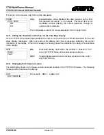
The 7707VR-8 can be individually configured to output black video with a user set standard if an input
video signal is lost. To select the video standard, select the desired option then select the OSTD menu.
This value is auto setup when valid inputs are detected.
CH1-CH8
OSTD
N270
P270
ASI
OFF
N270
SMPTE 259M-C, 270 Mb/s 4:2:2 Component 525 line, 4:3
P270
SMPTE 259M-C, 270 Mb/s 4:2:2 Component 625 line, 4:3
ASI
DVB-ASI
OFF
Signal Generator off
4.2.3. Displaying the Optical Power
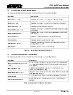
The 7707VR-8 module can measure and display the input optical power over a range of +5dBm to –
40dBm at increments of 1 dBm. To display the Input Optical Power press the pushbutton one or more
times until the
PWR
message is shown on the display. After one second the detected input optical power
will be shown (in units of dBm).
PWR
LOW
OVER
-40 to +1
LOW
Optical power measure is lower then operating range.
OVER
Optical power measure is higher then operating range.
-40 to +1
Optical input power within this range.
4.2.4. Signal BLOCK Configuration
Depress the Button and select the PSWD option. Actuate the toggle switch to achieve the correct code
number (Factory Default = 7154).
PSWD
0-9999
Code number (Factory Default = 7154).
PSWD
PWSL
0-9999
PWSL
Store a new passcode (0-9999) required for BLOCK
configuration. This menu is not available without entering the
correct passcode.


