6. Do not touch exposed parts, cables or connectors.
7. Do not dismantle, disassemble or modify any parts of the modules and do not remove
or alter in anyway the labels or markings on modules.
8. Do not step or walk on the modules. Doing so may damage and crack parts of
modules.
9. Do not expose modules to chemicals, for instance paints, solvents, adhesives.
10. Keep the modules away from inflammable gas, hazardous chemicals or flammable
explosive items.
11. Do not artificially focus light on the module.
5. Transportation and handling
Solar Modules are glass and contain very fragile silicon wafers inside them and must be
transported and handled with utmost care. Do not strike, drop or bend a solar module.
1. Never transport other items (e.g. Inverters) on top to a solar module pack.
2. Store the modules safely in cool and dry area. The packaging is not weatherproof.
3. Leave modules in their packaging until they are to be installed, the modules must avoid
rain and sand erosion after unpacking.
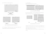
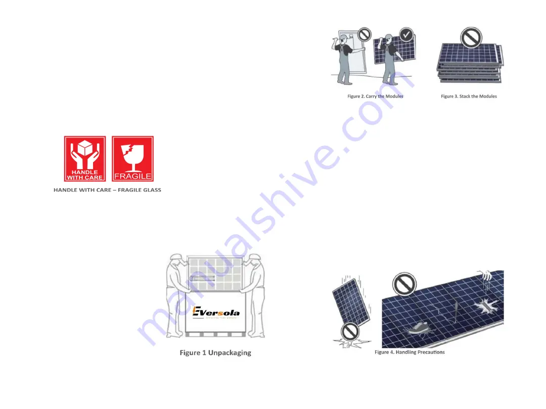
4. Unpacking PV modules from the original package:
Step 1: Remove securing straps.
Step 2: Remove the pallet lid.
Step 3: Unpack the modules one by one and stack
them(surface glass side down) without removeing
the cardboard edge protector.
Step 4: Remove the cardboard edge protector from the
modules before installing.
·03·
·04·
5. Check the module for damage due to transportation before the installation.
6. Use extreme caution if stacking modules for transport of less than a pallet at a time
line up the modules with their edge protectors in place and wraps, strap and fasten
them so that they cannot move around or rattle and fall. Care must be taken with
fasteners that secure modules but do not bend or damage the modules in any way.
7. The modules should be transported in their original packaging where possible with
any free space in the box securely filled with soft packaging materials to prevent the
panels from moving around.
8. Never move modules by pulling their cables.
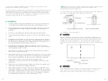
9. Carry the modules with both hands and with their glass surface facing the
operator when absolutely necessary (one operator available) (please see Figure 2).
Do NOT stack the modules back-sheet side down to avoid glass scratch and electric
shock risk (please see Figure 3).
10. Do not step or walk on the modules. Dong so may damage module (please see
Figure 4).
11. Do not carry wet or hot modules dropping a module from an height and impact
of falling tools may affect the electrical performance or break the module (see
Figure 4).


