12. The surface oxide layer of the frame may be damaged by sharp objects, do not
destroy or scratch the frame of the modules.
13. Glass surface, back-sheet and aluminum frame are susceptible to damage that could
affect the performance or integrity of the PV module; do not damage or scratch the
surfaces, and do not spray any non-validated chemicals paints, solvents or adhesive to
any of the surfaces, including the frame. Doing so may degrade performance or cause
irreparable damage and will void any applicable warranties.
6. Installation
1.
The electrical and mechanical installation must be comply with international and
local standards and principles including cable connection building codes etc.
2.
The mounting structures must be designed by qualified structural engineers, and
installation design and procedures shall be consistent with the relevant local
standards.
3.
Installers must be qualified and familiar with solar and electrical principles.
4.
The working ambient temperature range is -40℃ to +85℃ and Relative Humidity
≤85%.
5.
The modules shall be installed so as to maximize solar exposure and to minimize
shading by trees, buildings or other obstacles in the surrounding area. Generally in
the Northern hemisphere modules are ideally orientated to the south and in the
southern hemisphere modules orientated to the north.
6.
Notify Eversola of any damage to product immediately. Do not use or install
damaged modules. Damaged modules may cause fire or electric shock, resulting in
property damage, fire and or death.
7.
Do no disconnect or connect any cables under load, the bending cable radius of
Junction box must more than 43mm.
8.
Match the polarities of cables and terminals when making the connections, failure to
do so may result in damage to the module. Keep the connector dry and clean and
do not impact external force on the connector such as heavy snow, strong wind.
9.
The maximum modules of one PV string N=(The maximum system
voltage)/[(Voc)*1.25], note the Voc is the value at the lowest temperature in the
project sites.
10. Suitable over current protection devices (string fuses etc.) must be installed when
connecting 3 or more strings in parallel configuration.
11. Under normal conditions, a module may be able to produce voltage and current
higher than in standard test condition. Accordingly, when determining component
rated voltage, conductor ampacities, fuse current and size of controls connected to
the PV output, the short circuit current and open circuit voltage value marked on
this module shall be multiplied by a factor (safety factor) of 1.25.*
·06·
·05·
*Note:
The safety factor for component rated voltage, conductor ampacities, fuse
current and size of controls connected to the PV output is subject to the
meteorological conditions of project sites.
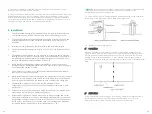
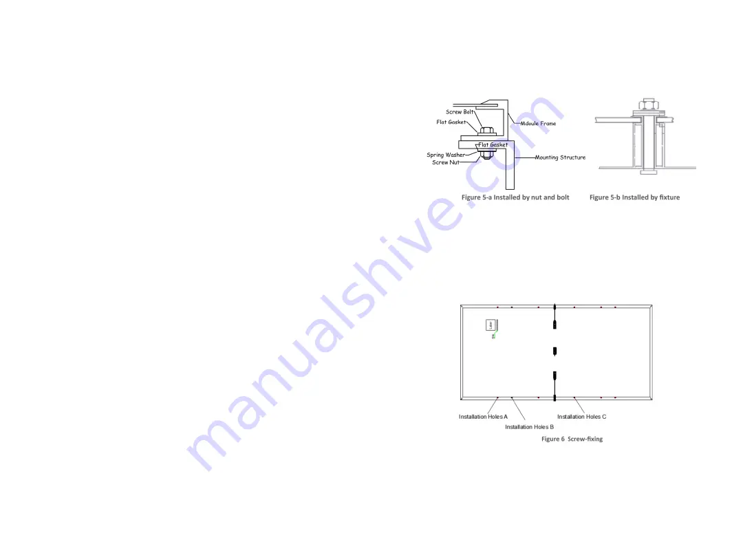
12. Select either method of fixing mentioned below depending on site conditions:
Screw-fixing system (Figure 5-a), Fixture-fixing system (Figure 5-b).
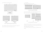
13. Installation method and location
1)
Screw-fixing:
Fixing the modules on the bracket at 12 border prefabricated installation holes
(figure 6). All the fastening pieces are made of stainless steel. Installing holes A must
be fixed with bolts and customer can choose one of the installation B or C to use.
Applied torque is recommended as 7-11 N*m for M6 (diameter is 6mm) screw in
installation holes C and 14-20 N*m for M8 (diameter is 8mm) screw in installation holes
A&B.
2) Fixture-fixing:
Fix the module safely and securely on the mounting structure. The length of clamp
should be 40mm minimum. Applied torque is recommended as 7-11 N*m for
M6(diameter is 6mm) screw. The clamp are made of aluminum alloy.


