·10·
·09·
18. It is better to use the modules with same specifications same color when
connected in series.
19. Artificially concentrated sunlight shall not be directed on the module.
20. Our modules have passed the salt mist and ammonia test (Please refer the test
report for detailed information) and can be installed in some corrosive
environments, e.g. sea side.
21. The modules should not be installed at the place which is less than 100 meters
from the seashore. If the distance of the seashore and the project site is
100~10000 meters, anti-corrosion application should be taken during the
installation and grounding processes.
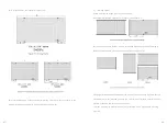
15. The minimum separation between two modules shall be more than 10mm; when
installing on the roof, the recommended separation between the modules and the
roof surface is 100mm to allow for air flow around the modules. When installing on
ground mounts keep ground clearances to more than 450mm.
16. Grounding
1)
Grounding method shall be consistent with the local standard and regulations. Any
grounding system/method, which is designed in accordance with relevant
international and local standards and regulations, such as UL2703, UL467,
IEC60335, NEC article 250 and section 690.V.43, etc. could be attached to the
modules.
2)
In order to prevent electrochemical corrosion, material in contact with module
frames, should be properly selected and galvanic isolation provided where
necessary.
3)
PID (Potential Induced Degradation) due to combined effects of high temperature,
high humidity and high voltage, is most likely to be observed in similar climates and
mounting surroundings such as India, Southeast Asia, floating designs. Expect for
equipment grounding, negative system grounding is strongly recommended as the
basic solution for PID phenomenon.
4)
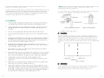
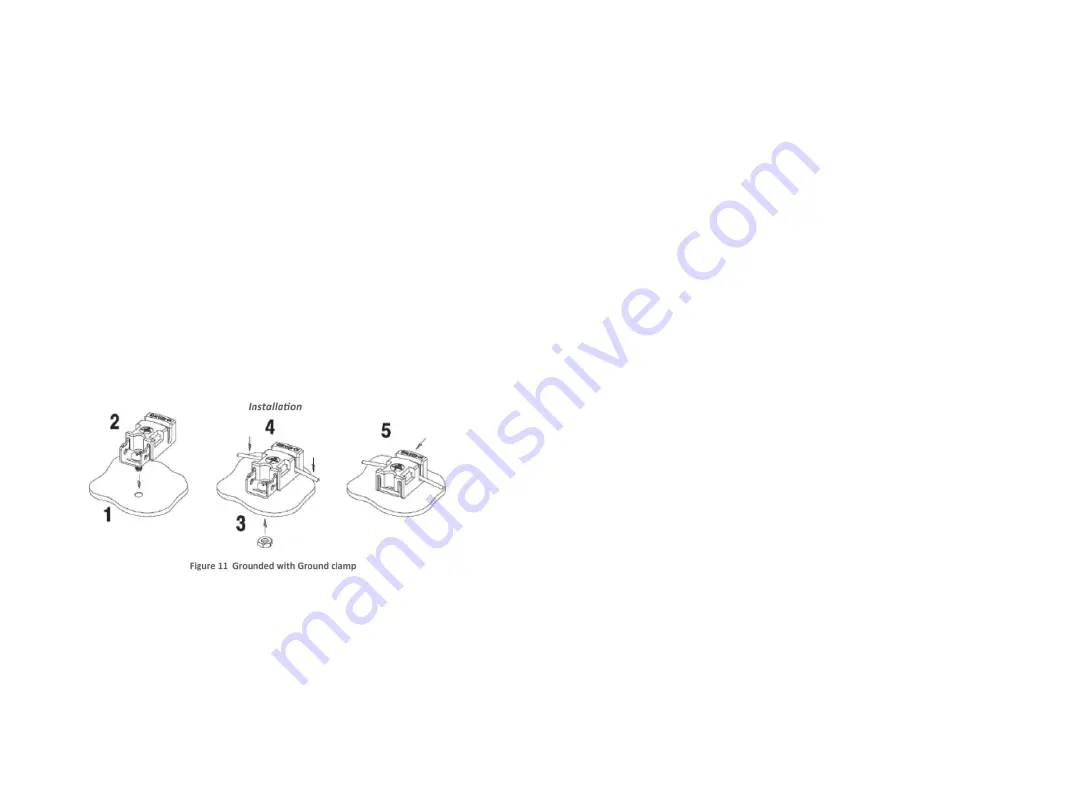
Grounding wire shall be the bare copper wire with simple surface treatment and no
insulation sleeve. Wire cable with cross-sectional area of 4mm
2
(10~12 AWG) and
ground clamp (such as Tyco, identification of product: 1954381-2) are
recommended(diagrammatic sketches are as follows).
17. When the connecting wires of the modules do not meet length requirements, a
correctly rated electrical cable that is designed and certified for long term outdoor
use along with the correct connectors can be used to extend the connections.
Match the same brand and type of module connectors to extend the connection.
The cross-sectional area for PV array wire must be no less than 4mm
2
, and the
connection system is IP67 rated.
7. Maintenance
1.
Do not touch any live parts of the array wires, uninsulated cable and the
connector. Use the safety equipment when working on solar equipment
(insulating tool, insulating gloves etc.).
2.
An opaque cloth or other non-abrasive material can be used for cover the
front of the modules to eliminate sunlight exposure and reduce the chance of
electrocution during maintenance when required.
3.
Cleaning instructions
Periodic cleaning is recommended for solar modules. The cleaning process
should be done by suitably trained professionals with the appropriate safety
equipment and procedures in place at all times. When cleaning the module
surface.
a) The following rules apply:
√ To reduce cold and hot shock clean panels at low irradiance time.
√ Only use soft cloths or sponges to clean the glass surface.
√ Only use clean water as the cleaning solvent.
√ The difference between water temperature and module temperature
should be in the range of -5℃ to +10℃.
√ Water pressure should be less than 1000Pa.
b) following notes should be taken into account:
√ No other chemical should be used in cleaning process.
√ No aggressive tools or coarse cleaning materials are permitted.
√ Do not step or walk on the modules.
√ Do not strike modules or subject modules to impact with tools or objects.
√ Isolate modules during cleaning and maintenance, the modules must not
be under load.
√ Do not touch exposed cables or connectors.
√ Do not remove dust in dry way (without water).


