background image

l


Prior to mounting, keep in mind that the motion

sensor is most sensitive to the motion, which is
across the detection field and less sensitive to the
motion, which moves directly towards the
detector.
(FIGURE 2)


     SENSOR                  SENSOR

LESS SENSITIVE      MORE SENSITIVE

SENSITIVITY TO MOTION

FIGURE 2

INSTALLATION

To facilitate installation, it is essential to get a drill and
a screwdriver ready.  Select a location for the unit based
on the coverage angles shown in FIGURE 3.

FIGURE 3

Install a wall switch adjacent to the power source.
(FIGURE 4 & 5)  This helps


you operate AUTO and

MANUAL OVERRIDE with ease. See page 4 for
further information.

Type I:

                   FIGURE 4

Type II:

FIGURE 5

2

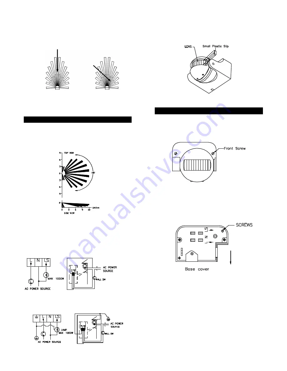
Note : The detection angle of ES34T can come up to180°.
However to reduce or localize its detection coverage, use
the small plastic slip(s) provided to cover up part(s) of the
LENS, thus reducing its detection angle. (FIGURE 6)

FIGURE 6

WIRING INSTRUCTION

(1)   Switch off the power source or wall switch.
(2)   Unscrew two front screws to detach the base cover

from the unit. (FIGURE 7)

(3)   Make use of the base cover as a template to mark

the position of two screw holes on the wall.  Drill
the wall and screw the base cover onto the wall
using suitable plastic wall plugs and screws
provided. (FIGURE 8).

FIGURE 8

(4)   Strip approximately 6-8mm insulating part of the

 wires from the power cord. Before connection,
 run the wires through the rubber seal provided.
 
 Note: The power cord must meet H05RN-F,
 1.0mm² requirement.


 3

Summary of Contents for ES34T

Page 1: ...uit protection or a suitable fuse l The unit can be installed only horizontally see the FIGURE 1a not vertically see the FIGURE 1b as shown in the below drawing HORIZONTAL VERTICAL FIGURE 1a 1b IMPORTANT Some local building codes may require installation of this product by a qualified electrician Check your local codes as they apply to your situation If the house wiring is of aluminum consult with...

Page 2: ... Type I FIGURE 4 Type II FIGURE 5 2 Note The detection angle of ES34T can come up to180 However to reduce or localize its detection coverage use the small plastic slip s provided to cover up part s of the LENS thus reducing its detection angle FIGURE 6 FIGURE 6 WIRING INSTRUCTION 1 Switch off the power source or wall switch 2 Unscrew two front screws to detach the base cover from the unit FIGURE 7...

Page 3: ...ight will turn on for about 1 minute to warm up Then it turns off l Walk through the detection area The light turns on when you move and turns off when you stop Wait for the light to turn off before moving again to test the sensor l Adjust the motion sensor to cover the desired detection area For a smaller coverage area point the sensor down for a larger coverage area point the sensor up 2 TIME AD...

Page 4: ...it back on TROUBLESHOOTING Light does not turn on l Confirm that you have made a correct wiring connection l Make sure that the bulbs have not burned out Light remains on l Make sure the wiring connection is correct l If you set the system to manual override remember that you must turn the wall switch off for at least 10 seconds to switch the sensor to automatic operation and turn off the lights l...

Reviews: