3405 Frame Manual
3405FR Series Fiber Optic SFP Frame
3405FR Series - 12
Revision 2.3
This NEBS compliant version of the frame is provided with the following components to facilitate
connection to a common bonding network.
Item#
Description
Qty.
1
M4 HEX Nut
2
2
#6 external tooth lock washer
4
3
Bonding Lug
1
Table 2-1: Bonding Parts Included with NEBS Compliant Version
•
This equipment is to be installed in the network telecommunication facilities.
•
Provide a dedicated connection from a common bonding network to this equipment by connecting
a stranded AWG #6 (16 mm
2
) copper wire to the bonding lug provided.
•
When using insulated wire, strip 7/8 inch (2 cm) of insulation.
•
Bare conductors of the bonding wire must be coated with antioxidant before crimp connections to
the bonding lug are made.
•
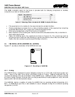
Fasten the bonding lug to the equipment as shown in Figure 2-10. The ground lug must be
secured as shown using four star washers (to prevent anti-rotation of the nuts) and two M4 nuts.
Tighten the nuts securely to provide a good bonding connection.
2.4.
FAN INSTALLATION AND REMOVAL (3405FAN)
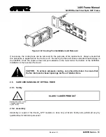
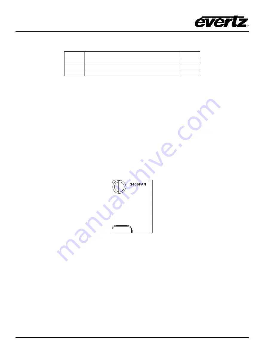
Figure 2-11 provides an illustration of the 3405FAN front view.
Figure 2-11: Front View of 3405FAN
2.4.1. Cooling
The 3405FR frame is designed to ensure adequate cooling for up to 40 watts of processing power per
frame. Fans at the sides of the frame accomplish forced air cooling. Adjacent equipment may be
mounted immediately to the top and bottom of the 3405FR frame. Additional module cooling is provided
by interior cooling channels to ensure that even fully loaded frames mounted adjacent to each other will
operate within the normal temperature range.
The 3405FAN module is capable of cooling the 3405FR from an operating ambient temperature of 0-
50°C. A 3405FAN-Q (quiet fan) is also available to ensure adequate cooling for an ambient operating
temperature of 0-30°C.


