background image

Frame Manual 

400FR Compact High Density Balanced Audio Distribution Frame 

 Revision 

0.2 


TABLE OF CONTENTS 


1.


OVERVIEW...............................................................................................................................1


2.


INSTALLATION ........................................................................................................................2


2.1.


COOLING ...................................................................................................................................... 2


2.1.1.


Fan Exhaust ...................................................................................................................... 2


2.2.


MOUNTING ................................................................................................................................... 2


2.3.


POWER ......................................................................................................................................... 2


2.3.1.


Turning the Power On and Off .......................................................................................... 3


2.4.


POWER SUPPLY STATUS INDICATORS ................................................................................... 3


3.


SPECIFICATIONS ....................................................................................................................5


3.1.


ELECTRICAL ................................................................................................................................ 5


3.2.


PHYSICAL ..................................................................................................................................... 5


3.3.


CERTIFICATION ........................................................................................................................... 5


3.4.


SIGNAL CONNECTIONS .............................................................................................................. 5


3.5.


STATUS INDICATORS ................................................................................................................. 6


3.6.


TALLY OUTPUT CONNECTOR.................................................................................................... 6


3.7.


TEMPERATURE............................................................................................................................ 6


4.


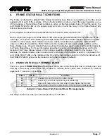
FRAME STATUS FAULT CONDITIONS ..................................................................................7


4.1.


FRAME STATUS TALLY TERMINAL BLOCK ............................................................................. 7


5.


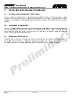
INSTALLING AND REMOVING THE MODULES ....................................................................8


5.1.


OPENING AND CLOSING THE FRONT PANEL.......................................................................... 8


5.2.


INSTALLING THE MODULES ...................................................................................................... 8


5.3.


REMOVING THE MODULES ........................................................................................................ 8


6.


SERVICING INSTRUCTIONS...................................................................................................9


6.1.


CHANGING THE FUSES .............................................................................................................. 9


Summary of Contents for 400FR

Page 1: ... STATUS INDICATORS 3 3 SPECIFICATIONS 5 3 1 ELECTRICAL 5 3 2 PHYSICAL 5 3 3 CERTIFICATION 5 3 4 SIGNAL CONNECTIONS 5 3 5 STATUS INDICATORS 6 3 6 TALLY OUTPUT CONNECTOR 6 3 7 TEMPERATURE 6 4 FRAME STATUS FAULT CONDITIONS 7 4 1 FRAME STATUS TALLY TERMINAL BLOCK 7 5 INSTALLING AND REMOVING THE MODULES 8 5 1 OPENING AND CLOSING THE FRONT PANEL 8 5 2 INSTALLING THE MODULES 8 5 3 REMOVING THE MODULES 8 ...

Page 2: ... Revision 0 2 6 2 REPLACING THE POWER SUPPLY 9 Figures Figure 1 1 400FR Front View 1 Figure 1 2 400FR Rear View 1 Figure 1 3 400PS Status Indicators 3 Figure 4 1 Locating the Power Supply Mounting Screw 10 Tables Table 2 1 Frame Status Tally Terminal Block Pin Assignments 7 ...

Page 3: ... either expressed or implied The only warranty offered by Evertz in relation to this product is the Evertz standard limited warranty stated in the sales contract or order confirmation form Although every attempt has been made to accurately describe the features installation and operation of this product in this manual no warranty is granted nor liability assumed in relation to any errors or omissi...

Page 4: ...Frame Manual 400FR Compact High Density Balanced Audio Distribution Frame Revision 0 2 This page left intentionally blank ...

Page 5: ...ppable and mates to the rear plane of the 400 frame which is completely passive The design approach eliminates the need to de cable the frame in the event of an electronics replacement Each slot of the 400FR provides ten high quality 3 pin terminal strip connectors that are used to interface to the processing module Features Dual hot swappable power supplies with integrated cooling Houses up to si...

Page 6: ...frame and draw air in the front and the exhaust out the rear of the frame CAUTION To ensure adequate cooling care should be taken to ensure that the fan inlets and exhaust openings are free of obstructions 2 2 MOUNTING The 400FR Rack frame requires 3 rack units i e 5 25 inches 133 mm of standard 19 inch 483 mm wide rack space To securely fasten the frame to the equipment rack make sure that all fo...

Page 7: ... OF THE MAINS PLUG MUST BE MAINTAINED 2 3 1 Turning the Power On and Off Each 400PS power supply is fitted with its own power switch When the switch is turned off the remaining power supply will power the 400FR frame To completely remove power from the frame both power supplies must be turned off 2 4 POWER SUPPLY STATUS INDICATORS Figure 2 1 400PS Status Indicators ...

Page 8: ...lt conditions If one of the power supplies malfunctions power cord disconnected power switch is off fuse is blown rear fan is stopped etc then its PSU STATUS LED will go Off and the red FRAME STATUS LED on both power supplies will turn On If the power supplies are fitted with green FRAME STATUS LEDs they will turn Off The PSU STATUS LED on the power supply that is functioning will remain On If the...

Page 9: ...wer supply Safety CSA Listed to CSA C22 2 No 60065 03 UL 60065 03 IEC 60065 2001 12 7th Edition Complies with CE Low voltage Directive 93 68 EEC EMC Complies with FCC part 15 class A Complies with EU EMC directive 89 336 EEC 3 2 PHYSICAL Height 5 25 133 mm Width 19 483 mm Depth 9 5 368 mm Module Capacity 16 slots Weight Approx 17lbs 7 7kg with 2 power supplies no slots occupied Approx 32lbs 14 5kg...

Page 10: ...o Distribution Frame Page 6 Revision 0 2 3 5 STATUS INDICATORS PSU status LED Local Error Failure LED 3 6 TALLY OUTPUT CONNECTOR 4 pin terminal relay N O N C for status fault alarm 2A 12 5VDC max 3 7 TEMPERATURE 0 40 C optimal performance 0 50 C operating ...

Page 11: ...the Frame Status buss On each module there is a jumper that disables sending local card fault information to the Frame Status Buss For more information about fault conditions on individual modules and for the location of the Frame Status Jumper on the module consult the individual chapter for the module For example if a module requires video or audio for its functionality and the video or audio is...

Page 12: ...2 INSTALLING THE MODULES Orient the module vertically such that the white card ejector is on the bottom Align the card with the card guide corresponding to the slot number where you installed the rear panel plate Carefully slide the module into the frame and press it completely into the rear panel connectors Make sure that the connectors are fully seated in the rear panel 5 3 REMOVING THE MODULES ...

Page 13: ... REPLACING THE POWER SUPPLY Each power supply is a complete assembly and includes the power supply cooling fan and one frame cooling fan In the event that the power supply or one of the fans malfunctions you will need to replace the power supply assembly with a spare one while the failed assembly is being repaired Do not run the frame for extended periods of time with one of the power supplies rem...

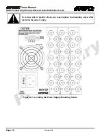
Page 14: ...y Balanced Audio Distribution Frame Page 10 Revision 0 2 To reduce risk of electric shock you must replace the mounting screw after replacing the power supply Model No 400FR MADE IN CANADA Figure 6 1 Locating the Power Supply Mounting Screw ...

Page 15: ... PSU MNT 3 Remove the power supply mounting screw 4 Open the front door of the frame and pull the power supply out of the frame 5 Reinsert the new power supply into the frame taking care that it is proper aligned with the card guides Press firmly to make sure that the power supply is fully seated into the rear panel connector 6 Reinstall the power supply mounting screw from the rear of the frame 7...

Page 16: ...Frame Manual 400FR Compact High Density Balanced Audio Distribution Frame Page 12 Revision 0 2 This page left intentionally blank ...

Reviews: