Frame Manual
400FR Compact High Density Balanced Audio Distribution Frame
Revision
0.2
Page - 9
6. SERVICING
INSTRUCTIONS
CAUTION – These servicing instructions are for use by qualified service
personnel only. To reduce the risk of electric shock, do not perform any
servicing instructions in this section of the manual unless you are qualified to
do so.
6.1.
CHANGING THE FUSES
The fuse holder is located inside the power entry module. To change the fuses, pull out the fuse holder
from the power entry module using a small screwdriver. The fuse holder contains two fuses, one for the
line and one for the neutral side of the mains connection. Pull out the blown fuse and place a fuse of the
correct value in its place. Use time delay 5 x 20 mm fuses rated for 250 Volts with a current rating of
4 amp. (T4AL250V) For your convenience there are spare fuses located in the vinyl pouch in the front of
this manual. Carefully reinsert the fuse holder into the power entry module.
Check that the line fuse is rated for the correct value marked on the rear panel.
Never replace with a fuse of greater value.
6.2.
REPLACING THE POWER SUPPLY
Each power supply is a complete assembly and includes the power supply cooling fan and one frame
cooling fan. In the event that the power supply or one of the fans malfunctions, you will need to replace
the power supply assembly with a spare one while the failed assembly is being repaired.
Do not run the frame for extended periods of time with one of the power
supplies removed. Proper cooling of the frame requires both power supplies to
be inserted into the frame, or one power supply and a 400PS-FM power supply
blank panel.
The 400FR power supplies are hot swappable and can be easily replaced from the front without
interrupting the signal integrity of the frame. Each power supply is capable of supplying full power to the
frame by itself. However, Evertz recommends running both power supplies for power redundancy and
cooling.
On frames with only one power supply, a 400PS-FM blank power supply module with cooling fan
must be
inserted into the second power supply space. The 400PS-FM contains a module cooling fan and baffles
to maintain proper airflow within the frame.
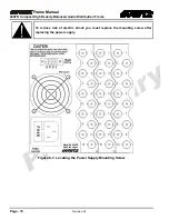
The power supply is secured into the frame by a machine screw through the rear panel (as shown in
Figure 6-1). This screw must be removed before the power supply can be extracted from the front.


