Model 5601MSC
Model 5601MSC Master SPG/Master Clock System
OPERATION
Revision 2.2
Page - 41
2.3.3.3. Syncro Time Reference
When two 5601MSC units are connected through a 5601ACO2 automatic changeover, a syncro
connection is established. Syncro is enabled using the
Syncro
menu item in the
GENERAL
root menu.
One of the 5601MSC units is designed the master and the other is the slave. The slave unit can receive
time and date from the master unit through syncro. See section 3.4 for information on syncro.
Syncro allows two 5601MSC units to share a single time reference such as GPS. The timestamp is
passed through the syncro connection and guarantees that the system clocks of the two units will be
synchronized. If the system clock of the slave units drifts more than 20 milliseconds from the master
unit, the slave unit will generate a
jam
event or jam warning, depending on the
Lock Type
setting. If the
syncro link is lost the slave unit will report a time unlocked fault.
2.3.3.4. LTC Time Reference
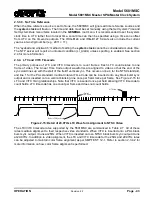
The 5601MSC can obtain time and date from an LTC input present on the GPIO DB15 connector. See
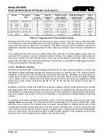
section 3.1.7 for wiring information. All output frame rates in Table 2-7 are supported as references.
Note that non real-time rates such as 23.98 and 29.97 nondropframe should be used with caution. See
section 2.3.4.1 for information on using dropframe timecode and the considerations required.
Date information can be decoded from the user bits (binary groups) of the LTC input. There are several
date formats in use and the date decoding method can be selected using the
VitcLtc Date
menu item.
Automatic detection of the date format is reliable for Legacy and SMPTE formats but may not work well
for Production date formats. If the user bits of the incoming LTC are not defined, or do not contain date
information the date decoder must be disabled (put into
No date
mode) to prevent false date decoding
and spurious
jam
events. When date decoding is disabled, the date can be set manually using the
Set
System Date
menu item located in the
GENERAL
root menu.
The 5601MSC will continuously compare the
system clock
to the incoming LTC time and date. When
a difference of more than 2 milliseconds is detected the 5601MSC will generate a
jam
event, or a jam
warning depending on the
Lock Type
setting. When a
jam
event occurs, the time read from the LTC
input is jammed into the
system clock
. At the same time, the LTC input time is jammed into the
timecode output clocks.
When the incoming LTC is jammed into a particular output timecode clock, it may be adjusted to
maintain color frame alignment and to match the output frame rate. See section 2.3.4.2 for more
information. If a particular timecode output is the same frame rate as the incoming LTC, the time is
copied directly into the output’s clock. If the timecode output is running at a different frame rate than the
LTC input, then the time is rounded to the nearest frame before being jammed into the output’s
timecode clock.
2.3.3.5. VITC Time Reference
The 5601MSC can read Vertical Interval Time Code (VITC) from a SMPTE ST 318 compliant color
black signal that is applied to the reference loop input. The VITC can be on any line of the incoming
color black video from line 6 to line 31. The VITC reader line is set by the
Vitc Line
menu item. The
5601MSC can read 25Hz VITC extracted from a PAL-B reference signal, and 29.97Hz dropframe VITC
extracted from an NTSC-M reference signal. See section 2.3.4.2 for information on using dropframe
timecode.
Date information can be decoded from the user bits of the VITC. The date format is selected using the
VitcLtc Date
menu item. The automatic detection mode works well for Legacy and SMPTE formats, but
may not work reliably for Production date formats. If there is no date information on the incoming VITC

