Model 5601MSC
Model 5601MSC Master SPG/Master Clock System
Page - 76
Revision 2.2
MASTER CLOCK
4.1.3. Panel Lock Function
Pressing the
PANEL LOCK
button will lock the front panel. The
PANEL LOCK
button will illuminate
indicating that the front panel keys are disabled. This is used to prevent accidental changes to the unit
once it has been configured. While the front panel is locked, the STATUS screens will still be
accessible. It will still be possible to press the STATUS button and view the various status screens but it
will not be possible to enter any other menu or change menu items. To unlock the panel, press the
PANEL LOCK
button while holding the SELECT button. The front panel will return to normal operation
and the
PANEL LOCK
button LED will turn off. Note that pressing HELP and
PANEL LOCK
at the
same time will also turn off the panel lock.
4.1.4. Front Panel LCD Displays
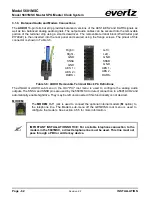
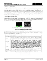
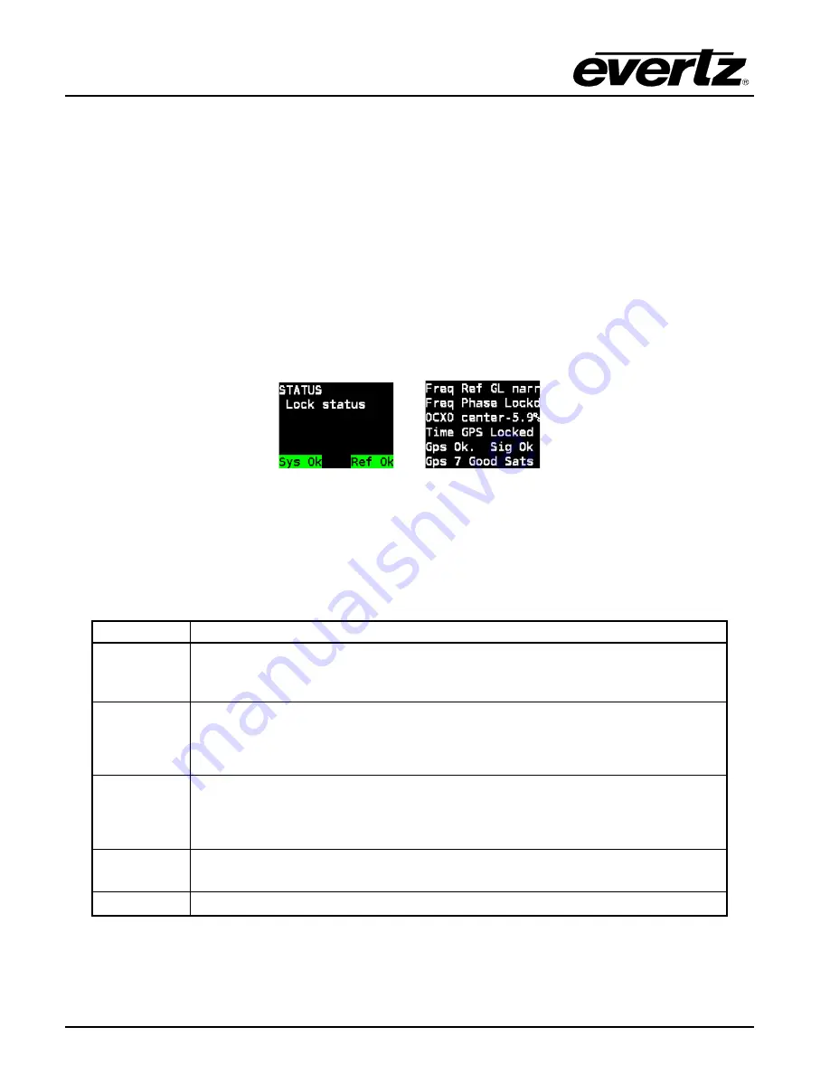
There are two full color LCD displays on the front panel. The left LCD indicates the current position in
the menu structure as well as system health status. The right LCD is used to display the menu system
and status screens. Figure 4-3 below shows the layout of the LCD screens.
↑
↑
System Status
Frequency Reference Status
Figure 4-3: LCD Displays in Status Screen
The left LCD display shows the current position in the menu tree. In the bottom-left corner the system
status is shown. A critical fault will appear in red blinking text. The possible system status messages
are summarized in Table 4-1 in order of severity:
Message
Description
Hw fail
Appears blinking red in the bottom-left corner. Indicates that an internal
hardware problem has been detected. It is advisable not to remove power from
the unit and to contact the factory immediately. See 2.2.3 for more information.
Temp Hi
Appears blinking red in the bottom-left corner. Indicates the internal
temperature of the unit has exceeded operating limits. Requires immediate
attention. May be due to excessive ambient temperature, fan failures, missing
power supply or fan module, or blocked exhaust vents on the side of the unit.
Ps fail
Appears blinking red in the bottom-left corner. Indicates that one of the power
supplies is not producing the correct voltage. Only applicable for dual power
supply installations. If only a single power supply is in use, make sure the
Number PS
menu item is set correctly (see section 4.5.9.5).
Warning
Appears in yellow text in the bottom-left corner. Indicates a non-critical fault in
the unit such as frequency or time reference missing, or fan failure.
Sys Ok
Appears in green text in the bottom-left corner. Indicates no system fault.
Table 4-1: System Status Messages

