Model 5601MSC
Model 5601MSC Master SPG/Master Clock System
Page - 62
Revision 2.2
INSTALLATION
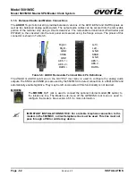
3.1.9. Balanced Audio and Modem Connections
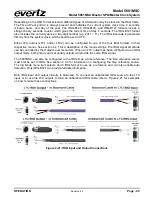
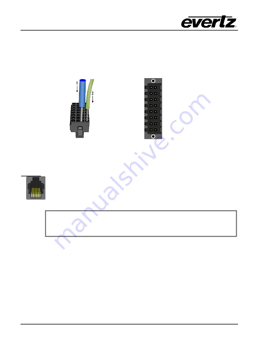
The
AUDIO
16-pin terminal strip provides balanced versions of the AES1/AES2 and DARS signals as
well as two balanced analog audio signals. The output audio cables can be secured into the removable
portion of the terminal strip using a small screwdriver. The removable terminal block (Weidmuller part
#174822) is then inserted into the rear panel and secured using the flange screws. The pinout of this
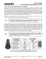
connector is shown in Table 3-6.
Right +
Left +
Right -
Left -
GND
GND
SNSA
SNSB
GND
GND
AES 1 +
AES 1 -
AES 2 +
AES 2 -
DARS +
DARS -
Table 3-6: AUDIO Removable Terminal Block Pin Definitions
The
ANALOG AUDIO
sub-menu in the
OUTPUT
root menu is used to configure the analog audio
outputs. The SNSA and SNSB pins are used by the 5601MSC to detect connection to a 5601ACO2 and
automatically enable highdrive. They may be left unconnected if this functionality is not desired.
MODEM:
The
MODEM
RJ11 jack is used to connect the optional internal modem (
M
option) to
the telephone line. The Modem sub-menu off the
GENERAL
root menu is used to
configure the modem. See section 4.5.5 for more information.
IMPORTANT INSTALLATION NOTICE: For a reliable telephone connection to the
modem in the 5601MSC, a direct telephone line must be used. This line must not
pass through a PBX or similar key device.

