background image

570ACO-X19-10G Series 

Quick Reference Guide 


TABLE OF CONTENTS 

Version 1.0


Page - iii


TABLE OF CONTENTS 

1.


OVERVIEW ................................................................................................................................... 1


2.


SPECIFICATIONS ......................................................................................................................... 3


2.1.


SERIAL DIGITAL VIDEO ...................................................................................................... 3


2.2.


IP INPUT ............................................................................................................................... 3


2.3.


SERIAL VIDEO OUTPUT ..................................................................................................... 3


2.4.


IP OUTPUT ........................................................................................................................... 3


2.5.


SWITCHING REFERENCE ................................................................................................... 3


2.6.


ELECTRICAL ....................................................................................................................... 3


2.7.


PHYSICAL ............................................................................................................................ 4


2.8.


ENCLOSURES ..................................................................................................................... 4


2.9.


ORDERING INFORMATION ................................................................................................. 4


3.


GETTING STARTED ..................................................................................................................... 5


3.1.


FRONT PLATE ..................................................................................................................... 5


3.2.


BACK PLATE ....................................................................................................................... 6


3.3.


CARE AND HANDLING OF OPTICAL FIBER ...................................................................... 7


3.4.


HARDWARE INSTALLATION .............................................................................................. 7


3.5.


570ACO-X19-10G INPUT/OUTPUT MAPPING .................................................................... 8


3.5.1.


App A Input/output mapping....................................................................................... 8


3.5.2.


App B Input/output mapping....................................................................................... 8


4.


WEB INTERFACE ......................................................................................................................... 9


4.1.


SYSTEM TAB ..................................................................................................................... 11


4.1.1.


Control Port Configuration ....................................................................................... 11


4.1.2.


Data Port Configuration ........................................................................................... 11


4.1.3.


Data Port Monitor ..................................................................................................... 12


4.1.4.


SFP Monitor ............................................................................................................. 13


4.1.5.


External Reference Monitor ..................................................................................... 13


4.1.6.


Genlock Control ....................................................................................................... 14


4.1.7.


Inband Control ......................................................................................................... 14


4.1.8.


RPC Timeout ........................................................................................................... 14


4.1.9.


Time Management ................................................................................................... 15


4.1.10.


Configuration Management ...................................................................................... 15


4.1.11.


Card Control ............................................................................................................ 15


4.2.


PRODUCT FEATURES ...................................................................................................... 16


4.2.1.


Product Features ..................................................................................................... 16


4.2.2.


License Control ........................................................................................................ 16


4.3.


ACS CONTROL .................................................................................................................. 17


4.3.1.


ACS Status .............................................................................................................. 17


Summary of Contents for 570ACO-X19-10G Series

Page 1: ...f Evertz Microsystems and is intended solely for the use of purchasers of the 570ACO X19 10G series product Evertz Microsystems expressly prohibits the use of this manual for any purpose other than the operation of the 570ACO X19 10G series product Due to on going research and development features and specifications in this manual are subject to change without notice All rights reserved No part of...

Page 2: ...This page left intentionally blank ...

Page 3: ...ird grounding prong The wide blade or the third prong is provided for your safety If the provided plug does not fit into your outlet consult an electrician for replacement of the obsolete outlet Protect the power cord from being walked on or pinched particularly at plugs convenience receptacles and the point where they exit from the apparatus Only use attachments accessories specified by the manuf...

Page 4: ... Class A digital device pursuant to Part 15 of the FCC Rules These limits are designed to provide reasonable protection against harmful interference when the equipment is operated in a commercial environment This equipment generates uses and can radiate radio frequency energy and if not installed and used in accordance with the instruction manual may cause harmful interference to radio communicati...

Page 5: ...y warranty offered by Evertz in relation to this product is the Evertz standard limited warranty stated in the sales contract or order confirmation form Although every attempt has been made to accurately describe the features installation and operation of this product in this manual no warranty is granted nor liability assumed in relation to any errors or omissions unless specifically undertaken i...

Page 6: ...570ACO X19 10G Series Quick Reference Guide Page ii Version 1 0 This page left intentionally blank ...

Page 7: ...AL FIBER 7 3 4 HARDWARE INSTALLATION 7 3 5 570ACO X19 10G INPUT OUTPUT MAPPING 8 3 5 1 App A Input output mapping 8 3 5 2 App B Input output mapping 8 4 WEB INTERFACE 9 4 1 SYSTEM TAB 11 4 1 1 Control Port Configuration 11 4 1 2 Data Port Configuration 11 4 1 3 Data Port Monitor 12 4 1 4 SFP Monitor 13 4 1 5 External Reference Monitor 13 4 1 6 Genlock Control 14 4 1 7 Inband Control 14 4 1 8 RPC T...

Page 8: ... 4 6 2 IP Output Advanced Control 25 4 6 3 IP Output Monitoring 25 4 7 VIDEO S2110 20 IP INPUT 26 4 7 1 Global Control 26 4 7 2 IP Input Control 26 4 7 3 IP Input Monitoring 27 4 7 4 IP Input IGMP Control 27 4 8 AUDIO S2110 30 IP OUTPUT 28 4 9 AUDIO S2110 30 IP INPUT 29 4 10 ANC S2110 40 IP OUTPUT 30 4 11 ANC S2110 40 IP INPUT 30 4 12 PTP CONTROL 31 4 12 1 PTP Control 31 4 12 2 PTP Monitor 32 4 13...

Page 9: ...S Status Failover Control 17 Figure 4 19 WebEASY ACS Status Output Control 18 Figure 4 20 WebEASY ACS Criteria Video Monitoring Control 19 Figure 4 21 WebEASY ACS Criteria Audio Monitoring Control 20 Figure 4 22 WebEASY ACS Criteria Audio Monitoring Per Group 21 Figure 4 23 WebEASY ACS Criteria Audio Monitoring Per Channel 21 Figure 4 24 WebEASY ACS Criteria ANC Monitoring Control 22 Figure 4 25 W...

Page 10: ...psulator Fault 36 Figure 4 48 WebEASY Notify ACS Notify ACS Fault 36 Figure 4 49 WebEASY Notify ACS Notify Clear Faults 37 Figure 4 50 WebEASY SNMP Trap SNMP Trap 37 Figure 5 1 WebEASY Upgrade Button on Top Menu Bar 39 Figure 5 2 WebEASY Firmware Upgrade Menu 39 Figure 5 3 WebEASY Firmware Upgrade Menu 40 Figure 5 4 VistaLINK Pro Version Information 41 Figure 5 5 VistaLINK Pro Upgrade Firmware 42 ...

Page 11: ...s and time periods to suit any application Features Benefits Signal Flow SMPTE 2022 7 on all 2110 main backup inputs Settable frame delay up to 14 frames per video path audio and ANC follow video Support slipless mode to auto sync videos from different inputs Program and Preview outputs can be manually overridden by the customer to select any input Clean video switch No TRS violations on video out...

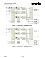
Page 12: ...570ACO X19 10G Series Quick Reference Guide Page 2 Version 1 0 Figure 1 1 570ACO X19 10G App A Block Diagram Figure 1 2 570ACO X19 10G App B Block Diagram ...

Page 13: ...24M 3Gb s STMPE 292M 1 5Gb s App B STMPE 292M 1 5Gb s Number of Outputs 6 Connector DIN Signal Level 800mV nominal DC Offset 0V 0 5V Return Loss 12 dB up to 1 5GHz 2 4 IP OUTPUT Ethernet Interface 4x 10GE SFP AppA B Encapsulation SMPTE2110 2 5 SWITCHING REFERENCE Reference Input 2x BNC on 570FR Analog 525 625 PTP IEEE1588 2008 via 10GbE interface 2 6 ELECTRICAL Voltage 12VDC Power 90 Watts EMI RFI...

Page 14: ...uide Page 4 Version 1 0 2 7 PHYSICAL Number of slots 2 2 8 ENCLOSURES S570FR 3RU chassis 570FR 1RU chassis 2 9 ORDERING INFORMATION 570ACO X19 10G Automatic change over with Audio Video monitoring 10GE I O and SDI outputs SFP sold separately ...

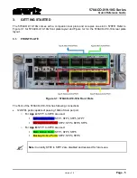
Page 15: ...r plate layout 3 1 FRONT PLATE Figure 3 1 570ACO X19 10G Front Plate The front of the 570ACO X19 10G has following connections 12xSFPs ports capable of passing 10Gb of data per port o For App A SFP1 to SFP8 are used Main Active Ports SFP1 SFP3 SFP5 SFP7 Backup Active Ports SFP2 SFP4 SFP6 SFP8 o For App B SFP1 to SFP8 are used Main Active Ports SFP1 SFP3 SFP5 Backup Active Ports SFP2 SFP4 SFP6 Note...

Page 16: ... has following connections 20 mini din connectors only first 6 dins are used for ACO1 ACO2 ACO3 o Din 1 for PGM SDI output and Din 2 for Prvw SDI output for ACO core 1 o Din 3 for PGM SDI output and Din 4 for Prvw SDI output for ACO core 2 o Din 5 for PGM SDI output and Din 6 for Prvw SDI output for ACO core 3 2 BNCs for Reference 1 power supply ...

Page 17: ...ller with 570ACO X19 10G installed in frame Before handling the card it is important to minimize the potential effects of static electricity It is therefore recommended that an ESD strap be worn Locate on the chassis 2 adjacent vacant slots Unpack the 570ACO X19 10G and separate the rear panel from the main card Locate on the rear of the rack the two slots and remove the blanking panels Insert the...

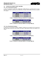
Page 18: ... App A SMTPE 2110 Input Mapping SFP Input Virtual SDI Input SFP1 2 1PGM 2PGM 3PGM SFP 3 4 1PRV 2PRV 3PRV Table 3 2 570ACO X19 10G App A SMTPE 2110 Output Mapping 3 5 2 App B Input output mapping In total there are 9 virtual SDIs 1A 1B 1C 2A 2B 2C 3A 3B 3C are converted from 2110 inputs Each ACS does failover switching of input A B C and output 2 SDIs PGM and PRV and identical 2110 outputs SFP Inpu...

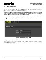
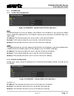
Page 19: ...ired network addresses for the control ports it can be completely configured using the web interface To do this simply type in the IP address of the Control Port on the 570ACO X19 10G module in the web browser Note We are assuming that the S570FR or 570FR frame is connected to the network and the computer is able to communicate to the frame on the Control Port IP address of the 570ACO X19 10G Figu...

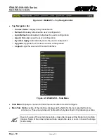
Page 20: ...tion o Upgrade Upgrade the Firmware s version of the product o Logout Logs the user out of the User Interface Figure 4 3 WebEASY Side Menu Side Menu Displays a menu of all tabs the user is able to monitor configure Main Tab Middle section of the interface displays all the fields for the item selected from the side menu These menu tabs and fields will be fully described in the following sections Du...

Page 21: ...0 tab shows the control IP address of the 570ACO This IP address is used when installed inside a 570FR frame with a 570FC present This IP address is set in the 570FC s webpage IP Address This Parameter allows the user to view the control port s IP address Netmask This Parameter allows the user to view the control port s Netmask Gateway This parameter allows the user to view the control port s Gate...

Page 22: ...received Ethernet Tx Bandwidth This field shows the transmitted Ethernet bandwidth Ethernet Tx Frames OK This field shows the number of error free frames transmitted Ethernet Tx Frames Err This field shows the number of errored frames transmitted Ethernet Tx Broadcast Frames This field shows the number of broadcast frames transmitted Ethernet Tx Unicast Frames This field shows the number of unicas...

Page 23: ...meter shows the SFP s received power level SFP Tx Power level This parameter shows the SFP s transmitted power level 4 1 5 External Reference Monitor Figure 4 8 WebEASY System External Reference Monitor For External Reference 1 2 Reference Status This field reports external reference lock status as Locked or unlocked Reference Present This field reports if an external reference is present or absen...

Page 24: ...s locked to the selected reference source 4 1 7 Inband Control Figure 4 10 WebEASY System In Band Control For SFP 1 6 SFP Port This control allows the user to select which SFP port will be used for RPC control Control Multicast IP This control allows the user to set a receive multicast IP address Tally Multicast IP This control allows the user to set a tally multicast IP address 4 1 8 RPC Timeout ...

Page 25: ...oad save the card s current configuration on a local PC Import Configure File This upload control allows the user to load a previously saved configuration file to the card 4 1 11 Card Control Figure 4 14 WebEASY System Card Control Card Alias This text box allows the user to enter a custom card name which will be shown on the top left hand corner of the card s webpage in yellow Purge Card This con...

Page 26: ...t Feature Supported This parameter shows you if the listed product feature is enabled or disabled 4 2 2 License Control Figure 4 15 WebEASY License Control Product Features Export Product License File Clicking the Download button allows the user to download the product license file license txt to your PC Import Product License File This control allows you to upload a product license file Product S...

Page 27: ...tus Input Control A C Enable These controls allow the user to enable or disable Auto Clean Switch ACS individually 4 3 3 Failover Control Figure 4 18 WebEASY ACS Status Failover Control Revertive Mode This dropdown allows the user to Enable Disable Revertive mode If revertive mode is enable with priority 1 A and priority 2 B currently PGM input source is B and then you route input stream A then cu...

Page 28: ...tput to mute or last frame if the Input lost Preview IP Output at loss of video This dropdown menu allows the user to set Preview IP Output to mute or last frame if the Input lost Second Output From this dropdown menu user can set second output to PGM or Preview Slipless mode This dropdown menu allows the user to enable or disable Slipless mode At slipless mode enable ACO will auto align input str...

Page 29: ...ion This field allows to set the video freeze duration between 1 to 1000 frames Video Freeze Timeout This field allows to set video freeze timeout between 1 to 1000 frames Video Packet Error Failover Using this dropdown menu user can enbale disable Failover when there is packet error To get failover on video packet error video packet error should be enable Video Packet Error duration This Field al...

Page 30: ...sing Timeout This field allows to set Audio Missing Timeout between 1 to 100000ms Audio Silence Duration This field allows to set Audio Silence duration between 1 to 100000ms Audio Silence Timeout This field allows to set Audio Silence Timeout between 1 to 100000ms Audio Packet Error Duration This field allows to set Audio Packet Error Duration between 1 to 100000ms Audio Packet Error Timeout This...

Page 31: ...This conrol allows the user to enable disable Failover when audio group is missing Audio Packet Error Failover This control allows the user to enable disable Failover when there is Audio Packet Error 4 4 4 Audio Monitoring Per Channel Figure 4 23 WebEASY ACS Criteria Audio Monitoring Per Channel For 16 Channels Audio Silence Failover This control allows to Enable Disable Failover when Audio is Sil...

Page 32: ... 1000 frames Close Caption Missing Failover This control allows to Enable Disable Failover when Close Caption is missing Close Caption Missing Duration This field allows to set Close Caption Missing duration betweeen 1 to 1000 fames Close Caption Missing Timeout This field allows to set Close Caption Missing Timeout between 1 o 1000 frames SCTE104 Missing Failover This control allows the user to E...

Page 33: ...r SDI Output SDI Output Buffer Mode This dropdown menu allows the user to select the buffer mode Low Latency Frame Buffer Line Buffer for SDI output SDI Output Pop Suppressor This dropdown allows the user to Enable Disable the Pop Suppressor SDI Output Frame Delay In this field User can set Number of frames delay between 0 to 14 Frames 4 5 2 SDI Output Monitoring Figure 4 26 WebEASY SDI Control SD...

Page 34: ... 4 28 WebEASY Video S2110 20 IP Output IP Output Control For PGM 1 to 3 and Prvw 1 to 3 PGM Program outputs for ACO1 ACS1 ACO2 ACS2 and ACO3 ACS3 respectively Prvw Preview outputs for ACO1 ACS1 ACO2 ACS2 and ACO3 ACS3 respectively IP Output Status This field indicates if IP output is enabled or disabled for Main and Back up path IP Output Destination IP Address This field allows the user or contro...

Page 35: ... port IP Output Type of Service This field allows the user or control system to assign the type of service IP Output Time to Live This field allows the user or control system to assign the output Time to live TTL value 4 6 3 IP Output Monitoring Figure 4 30 WebEASY Video S2110 20 IP Output IP Output Monitoring For PGM 1 to 3 and Prvw 1 to 3 refer to 4 6 1 for details IP Output Present This field i...

Page 36: ...or 1A to 3C refer to 4 5 1 for details IP Input Status This field shows the IP input status as Enabled or Disabled based on the routing set for the card IP Input IP Address This field shows the IP input IP address IP Input UDP Port This field allows the user or control system to assign the corresponding UDP port Preset IP Address This field allows the user or control system to assign the input IP ...

Page 37: ...n Mbps Video Standard This field show video standard of IP Input RTP Present This field shows that RTP is present or not for IP Input RTP Sequence Error This field that there are RTP sequence Errors present or not Clear This button allows the user to clear reset all the monitoring statistics 4 7 4 IP Input IGMP Control Figure 8 4 WebEASY Video S2110 20 IP Input IP Input IGMP Control For 1A to 3C r...

Page 38: ... 1 to 3 and Prvw 1 to 3 refer to 4 6 1 for details IP Output Status This parameter shows the status of the IP output Destination IP Address This parameter allows the user or control system to assign an output IP address multicast address Destination UDP Port Number This parameter allows the user or control system to assign the output UDP port number ...

Page 39: ...IP Input Enable This field displays the IP input status as Enabled or Disabled based on the routing set for the card IP Input IP Address This field allows the user or control system to assign the IP input IP address IP Input UDP Port This field allows the user or control system to assign the IP input UDP port IP Input Present This field indicates if the IP input is present or not ...

Page 40: ...ows the user or control system to assign the output UDP port number 4 11 ANC S2110 40 IP INPUT Figure 4 37 WebEASY ANC S2110 40 IP Input Tab For 1A to 3C refer to 4 5 1 for details IP Input Status This field shows the IP input status as Enabled or Disabled based on the routing set for the card IP input IP Address This field allows the user or control system to assign the IP input IP address IP Inp...

Page 41: ...dropdown menu allows the user to select which SFP port to use for a main a backup PTP source Domain Number This field allows the user to set the PTP domain number which identifies a group of devices that talk together Priority 1 This field allows the user to set the priority 1 value for PTP control Priority 2 This field allows the user to set the priority 2 value for PTP control ...

Page 42: ...unce Lost Shows if any announcement has been lost It should be zero Sync Received Shows the number of PTP sync has been received Sync Lost Shows if any sync has been last Follow_up Received Shows the number of follow_up requests received Follow_up Lost Shows if any follow_up request has been lost Delay_Req Shows the number of Delay has been requested Delay_Resp Received Shows the number of Delay h...

Page 43: ...re 4 40 WebEASY Video Notify Tab For 1A to 3C refer to 4 5 1 for details Video Traps This control is used to turn traps On or Off Video Faults This displays whether a fault is currently present or not 4 14 AUDIO NOTIFY 4 14 1 Audio Monitoring Control Figure 4 41 WebEASY Audio Notify Audio Monitoring Control For 1A to 3C refer to 4 5 1 for details Audio Silence Level In this field user can set sile...

Page 44: ...to 3C refer to 4 5 1 for details Audio Traps This control is used to turn traps On or Off Audio Faults This displays whether a fault is currently present or not 4 14 3 Audio Stream Notify In this section users can set the trap for Audio streams1 4 for Audio Missing and Audio Packet Error Figure 4 43 WebEASY Audio Notify Audio Stream Notify For 1A to 3C refer to 4 5 1 for details Audio Traps This c...

Page 45: ...ection of the System tab Audio Faults This monitor will display green when there is no fault on the audio and red for a fault indication 4 15 ANC NOTIFY In this tab user can Enable Disable the traps for VANC Packet Missing Close Caption Missing and SCTE104 Missing by selecting True false from dropdown menu Figure 4 45 WebEASY ANC Notify For 1A to 3C refer to 4 5 1 for details ANC Traps This contro...

Page 46: ...ulator Fault For 1A to 3C refer to 4 5 1 for details Decapsulator Trap This control allows to enable or disable decapsulator traps Decapsulator Fault Present This indicator displays whether a fault is currently present or not 4 16 3 ACS Fault In this section users can set the traps for PGM failover Preview Failover Active PGM Output Source Change and Active Preview Output change for all three ACSs...

Page 47: ...r allows the user to view current trap destinations to set more trap destinations Number of Valid Trap Destination This parameter shows the current number of valid trap destinations present Add Trap Destination This parameter allows the user to add an IP to the trap destination list Make sure you click the Apply button for changes to take effect Remove Trap Destination This parameter allows the us...

Page 48: ...570ACO X19 10G Series Quick Reference Guide Page 38 Version 1 0 This page left intentionally blank ...

Page 49: ...for Password On the top of the web page for the 570ACO X19 10G there is a tab labeled Upgrade The Upgrade tab is used to check current firmware version and upload the latest firmware Figure 5 1 WebEASY Upgrade Button on Top Menu Bar Selecting the Upgrade tab will open a new window as shown in Figure 5 2 where the current firmware version is shown Should the firmware version be outdated the user wi...

Page 50: ...ence Guide Page 40 Version 1 0 Figure 5 3 WebEASY Firmware Upgrade Menu Once selected click Open Step 1 to advance to next step Click Upgrade Step 2 and watch progress bar for status Once completed the device will automatically restart ...

Page 51: ...k on Version Information 2 In version information window Select 570ACO X19 10G under hardware Figure 5 4 VistaLINK Pro Version Information 3 User can check current jar version and current firmware version loaded on 570ACO 4 To upgrade firmware first check the checkbox for 570ACO under Upgrade column 5 Then click on Upgrade and browse to locate image file 6 Once selected click on OK to advance to n...

Page 52: ... 8 Then after some time you will see Upgrade logon window with default username customer and password customer Click on Ok Figure 5 6 VistaLINK Pro Upgrade Logon 9 Once completed the device will automatically reboot and you ll see following window in VistaLINK Pro Figure 5 7 VistaLINK Pro Upgrade completed ...

Reviews: