7706LT
Extended L-Band RF Fiber Transmitter
Page - 16
Revision 1.1
6.1.
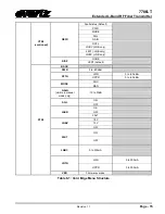
7706LT CONTROLLED PARAMETERS
To change the 7706LT parameters, select the
CTRL
menu item in menu level 1. The toggle switch may
then be used to select the parameter to change as described below.
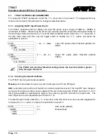
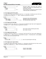
6.1.1. Adjusting the RF Input Power Alarm
The 7706LT measures and can display the input RF power over a range of 0dBm to –60dBm in
increments of 1dBm. Alarms may be set for high and low input RF power that will appear locally on
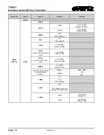
the card edge LEDs (see Section 4). To set the alarm threshold points, select the
CTRL
menu item in
the first menu level and then use the toggle switch to display the
RFTH
option
and press the
pushbutton to select it.
CTRL
0
to
–60
dBm
Lower RF power alarm threshold (default -60
dBm).
RFTH
LWR
0 to –60 dBm
CTRL
0
to
-60
dBm
Upper RF power alarm threshold (default
0dBm).
RFTH
UPPR
0 to -60 dBm
The 7706LT will not allow threshold settings where the lower threshold is greater
than the upper threshold.
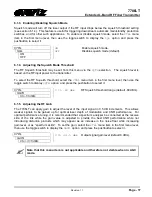
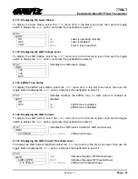
6.1.2. Selecting the Input Gain Mode
The 7706LT has two gain modes available:
Manual
gain mode allows the user to select a fixed gain level for the RF signal.
AGC
(automatic gain control) will maintain a constant output level even if the input RF level changes,
as long as this input level does not go outside of the AGC hold range (the 7706LT has from 0 to +31.5
dB of gain available to automatically apply to the incoming signal to maintain the target level). The
AGC target level is user adjustable (see Section 6.1.6).
To select the gain mode, select the
CTRL
menu item in the first menu level, then use the toggle switch
to display the
MODE
option
and press the pushbutton to select it.
CTRL
AGC
AGC mode (default).
MAN
Manual mode.
MODE
AGC
MAN

