7800EMR-ALINK2
User Manual
Revision 1.0
Page - 7
4.
FRONT CARD EDGE CONTROLS AND LEDS
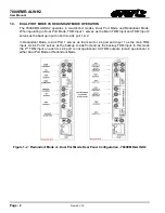
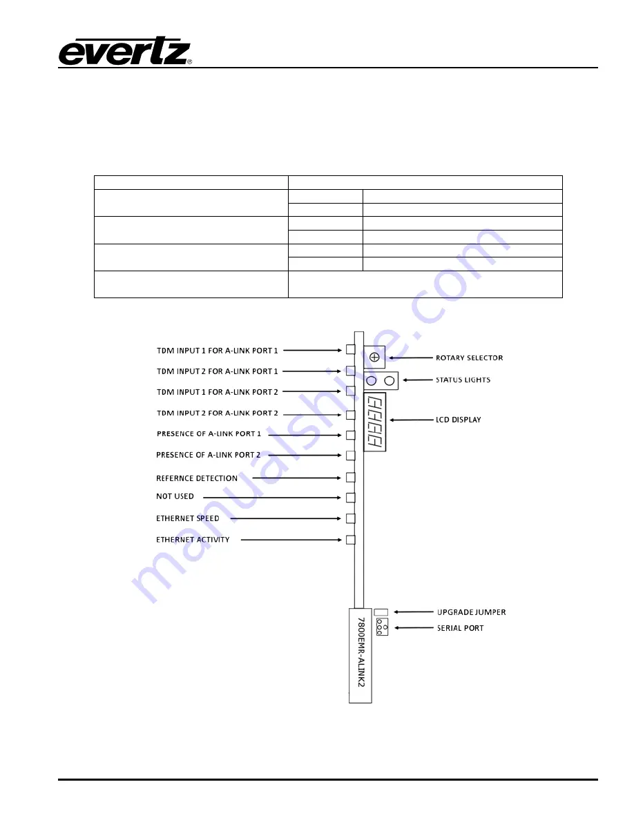
The 7800EMR-ALINK2 front card edges have some key controls and indicators that can help in the
installation and debugging processes. Figure
4-1 shows the card edges and describes the expected
behavior of each component.
Component
Description
A-Link Presence
Red
Green
TDM Input
Red
Green
Reference Detection
Red
Reference Lost
Green
Reference Locked
Rotary Switch
Switched the display to view firmware version, IP
address and temperature.
Table
4-1 : Description of 7800EMR-ALINK2 Card Edge
Figure
4-1 : Front Card Edges of 7800EMR-ALINK2
Summary of Contents for 7800EMR-ALINK2
Page 2: ...This page left intentionally blank ...
Page 8: ...7800EMR ALINK2 User Manual Page iv Revision 1 0 This page left intentionally blank ...
Page 12: ...7800EMR ALINK2 User Manual Page 4 Revision 1 0 This page left intentionally blank ...
Page 14: ...7800EMR ALINK2 User Manual Page 6 Revision 1 0 This page left intentionally blank ...
Page 16: ...7800EMR ALINK2 User Manual Page 8 Revision 1 0 This page left intentionally blank ...
Page 20: ...7800EMR ALINK2 User Manual Page 12 Revision 1 0 This page left intentionally blank ...
Page 56: ...7800EMR ALINK2 User Manual Page 48 Revision 1 0 Figure 8 2 Sample FTP Upgrade Window ...

