background image

9780SLKE2-H264HD 

9780SLKE2-H264HD Dual HD/SD-SDI StreamLINK™ MPEG2/H.264/AVC Encoder 


Page 2 

Revision 1.1


2. 

GETTING STARTED 

1. 

Set up inputs and outputs: 

a.  Connect one HD-SDI input to the BNC marked HD-SDI INPUT1 on the rear panel and the 

second input to the BNC marked HD-SDI INPUT2.  

 
b.  Connect  the  IP management Ethernet cable to  the CONTROL Ethernet port on the rear 

panel.  


c.  To access the encoders’ IP output, connect an Ethernet cable to the DATA MAIN Ethernet 

port on the rear panel. This can be connected to the decoder directly or via an Ethernet 
switch.  


2. 

Configure the encoder:  

a.  Verify that the computer is on the same control/management subnet as the encoder.  For 

example, if the encoder’s control/management IP address is 192.168.77.100, set the PC to 
192.168.77.xxx where xxx is user’s choice.  

 
b.  Open a web browser and navigate  to the Control IP address of the encoder, for example, 

192.168.77.100. 

 
c.  Let us assume that Profile 1 applies to encoder 1 and Profile 2 applies to encoder 2. Go to 

the Output tab and set the Transport Stream, TS, Bitrate and the Destination IP Address 
and Port for both profiles. For example, the Destination IP Address and Port can be 
239.79.0.100 and 1234. Unicast or multicast operation is strictly based on the destination IP 
address entered here. 

 
d.  Navigate  to the

  Encoder 

tab, select Profile 1 in the dedicated drop down box and set the 

desired Video Bit Rate in bits/second (for example, 10000 for 10Mbps) and the other 
encoding parameters listed in the interface. Click on 

“Save in Profile 1”

  button. Then 

select 

Profile 2

, set the encoding parameters for Profile 2 and click on 

“Save in Profile 2”

Note that parameters marked with a red star require the specific encoder  to be restarted. 
From the 

System 

tab, select the encoder from the drop down menu and select the 

Restart


button. 

 
e.  Navigate to the 

Inputs

 tab, select 

Profile 1

 in the dedicated drop down box and select the 

desired 

Video Standard

 and 

Display Aspect Ratio

, and any 

1 of 8 audio types

. Click on 

“Save in Profile 1” 

button. Select 

Profile 2,

  set the parameters and click on 

“Save in 

Profile 2”

 button. 

 
f.  Go to the 

Control

  tab. Both encoders can be activated by means of clicking on the 

“Activate All”

 button. It is also possible to activate one encoder at a time by clicking on the 

first of the three buttons on the left hand-side of the interface

. The two other buttons 

allow for the pausing and restarting of the encoder application


Summary of Contents for 9780slke2-h264hd

Page 1: ...ertz com Version 1 1 February 2012 The material contained in this manual consists of information that is the property of Evertz Microsystems and is intended solely for the use of purchasers of the 9780SLKE2 H264HD Evertz Microsystems expressly prohibits the use of this manual for any purpose other than the operation of the device All rights reserved No part of this publication may be reproduced wi...

Page 2: ...This page left intentionally blank ...

Page 3: ...ird grounding prong The wide blade or the third prong is provided for your safety If the provided plug does not fit into your outlet consult an electrician for replacement of the obsolete outlet Protect the power cord from being walked on or pinched particularly at plugs convenience receptacles and the point where they exit from the apparatus Only use attachments accessories specified by the manuf...

Page 4: ...IGITAL DEVICE OR PERIPHERAL This equipment has been tested and found to comply with the limits for a Class A digital device pursuant to Part 15 of the FCC Rules These limits are designed to provide reasonable protection against harmful interference when the equipment is operated in a commercial environment This equipment generates uses and can radiate radio frequency energy and if not installed an...

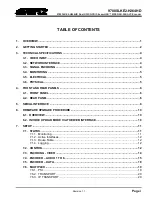
Page 5: ...ELECTRICAL 5 3 6 PHYSICAL 5 4 FRONT AND REAR PANELS 6 4 1 FRONT PANEL 6 4 2 REAR PANEL 6 5 SERIAL INTERFACE 8 6 FIRMWARE UPGRADE PROCEDURE 10 6 1 OVERVIEW 10 6 2 INVOKE UPLOAD MODE VIA THE WEB INTERFACE 10 7 SETUP 11 7 1 STATUS 11 7 1 1 Monitoring 11 7 1 2 Active Interfaces 12 7 1 3 Route Table 12 7 1 4 Logging 12 7 2 CONTROL 12 7 3 ENCODING VIDEO 14 7 4 ENCODER AUDIO 1 TO 8 15 7 5 ENCODER DATA 18...

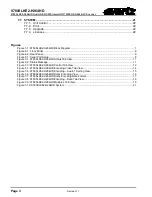
Page 6: ...ial Port Setup 8 Figure 7 1 9780SLKE2 H264HD Status Tab View 11 Figure 7 2 Status Message 11 Figure 7 3 9780SLKE2 H264HD Control Tab View 12 Figure 7 4 9780SLKE2 H264HD Encoding Video Tab View 14 Figure 7 5 9780SLKE2 H264HD Encoding Audio 1 Setting View 15 Figure 7 6 9780SLKE2 H264HD Dolby Encoding View 16 Figure 7 7 9780SLKE2 H264HD Dolby Encoding Data Format 17 Figure 7 8 9780SLKE2 H264HD Encodi...

Page 7: ...of future performance either expressed or implied The only warranty offered by Evertz in relation to this product is the Evertz standard limited warranty stated in the sales contract or order confirmation form Although every attempt has been made to accurately describe the features installation and operation of this product in this manual no warranty is granted nor liability assumed in relation to...

Page 8: ...9780SLKE2 H264HD 9780SLKE2 H264HD Dual HD SD SDI StreamLINK MPEG2 H 264 AVC Encoder Page iv Revision 1 1 This page left intentionally blank ...

Page 9: ... of the device is fully flexible allowing the user to configure various encoding parameters including bitrate GOP size visual filter effects network interface and more This device can also de embed the audio from the incoming video signal and apply MPEG 2 Layer II encoding or optional Dolby Pulse encoding for up to 8 audio services The 9780SLKE2 H264HD has a dedicated control port that offers a bu...

Page 10: ...s For example the Destination IP Address and Port can be 239 79 0 100 and 1234 Unicast or multicast operation is strictly based on the destination IP address entered here d Navigate to the Encoder tab select Profile 1 in the dedicated drop down box and set the desired Video Bit Rate in bits second for example 10000 for 10Mbps and the other encoding parameters listed in the interface Click on Save ...

Page 11: ...r example per above a decoder would need to receive on IP 239 79 0 100 and Port 1234 b Make sure the decoder input is selected correctly to IP input 4 Troubleshooting should the system not respond as expected confirm or perform the following procedure a Control management interface can be pinged b Both data interfaces can be pinged Verify that the destination IP address and port values match on th...

Page 12: ...f Interfaces 3 electrical Main Data streaming Back up Data streaming Control HTTP web browser SNMP through VistaLINK Standard Ethernet 10 100 base T IEEE 802 3U standard for up to 100Mb s Connector RJ 45 3 3 SIGNAL ENCODING Video Encoding Engine H 264 AVC MPEG2 Audio Encoding Engine MPEG 1 Layer II Dolby E Pass Through Dolby Digital AC 3 Pass Through Optional Dolby Pulse Traffic Shaping Constant b...

Page 13: ...ard detection Audio presence detection Error Notification HTTP web browser status page Card edge LED 3 5 ELECTRICAL Voltage Auto ranging 100V 240V AC 50Hz 60Hz Power 60W EMI RFI Complies with FCC Part 15 Class A EU EMC directive Safety TUV listed complies with EU safety directive 3 6 PHYSICAL Dimensions 19 W x 1 75 H x 18 75 D 483mm W x 45mm H x 477mm D Weight 12lbs 4 4kg ...

Page 14: ...hat the unit is powered ON 4 2 REAR PANEL There are various interfaces on the back panel of the 9780SLKE2 H264HD Figure 4 2 Rear Panel 1 Serial A This is a 9 pin DB male connector which is a serial interface to the encoder This can be hooked to any serial port client application e g Hyper Terminal or Tera Term The settings required on the serial client application are as per the picture below 2 VG...

Page 15: ...nt data port which is an exact copy of the main data Output IP stream from encoders 1 2 are present on both the Ethernet ports 6 HD SD SDI Input 1 2 These BNC connectors are used to feed a baseband signal to Encoder 1 2 respectively 7 Control The third Ethernet port on the rear panel of the encoder is labelled Control This is used to control the encoder via Web Interface 8 Power Supply Sockets The...

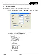
Page 16: ...illustrated in Figure 5 1 Figure 5 1 Serial Port Setup 2 Press enter You will see a login prompt like this debian3480 login Use customer for both login ID and password 3 Once you are logged in you will see the following menu Eth3 settings address 192 168 192 28 netmask 255 255 255 0 gateway 192 168 192 1 DHCP IS TURNED OFF 1 Change IP 2 Change netmask 3 Change gateway 4 Turn DHCP ON OFF 5 Change e...

Page 17: ...o select eth0 Press 5 and enter and then press 0 and enter eth0 is for Data Main interface eth1 is for Data Redundant interface eth3 is for Control network Please Note Options 6 and 7 are for Evertz support staff only It is recommended that these settings are not handled by the user Once the control IP address eth3 is set on the encoder set the correct IP address of the PC so that the encoder port...

Page 18: ...d using the web interface You will need the following equipment in order to update the Firmware PC where the web interface that controls the encoder has been opened following the steps specified in section 6 2 New firmware supplied by Evertz 6 2 INVOKE UPLOAD MODE VIA THE WEB INTERFACE 1 Select the System tab on the web interface 2 Click on Choose File at the bottom of the System tab next to Upgra...

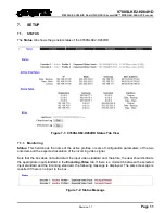
Page 19: ...tive profiles or sets of configuration parameters of the two encoders and the expected resolution of the incoming video signal Note that the box does not auto detect the input video standard and therefore the user should indicate the appropriate input standard in the Encoding Video tab If there is a mismatch between the selected input standard and the incoming standard the following message is dis...

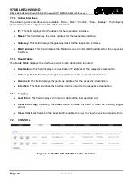
Page 20: ...nterface 7 1 3 Route Table The Route Table displays the interface to which each destination is routed Destination This field displays the destination IP address for the respective destination Gateway This field displays the gateway address for the respective destination Genmask This field displays the genmask address for the respective destination Interface This field identifies the interface that...

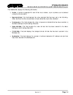
Page 21: ...b Note that the encoder does not auto detect the input video standard Compression This field displays the video compression standard that has been selected in the Basic Settings in the Encoding Video tab Video Bit Rate This field displays the video bit rate that has been selected in the Basic Settings in the Encoding Video tab TS Bit Rate This field displays the transport stream bit rate that has ...

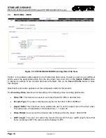
Page 22: ...nges Note that this procedure applies to all the configuration tabs for this product The Encoding Video tab allows for the setting of the following video encoding parameters Video PID This field can be used to set Video Packet ID PID in decimal form Encoder Type The video compression engine can be either H 264 or MPEG 2 Aspect Ratio This drop down menu enables the user to set the aspect ratio of t...

Page 23: ...rmal medium or low 7 4 ENCODER AUDIO 1 TO 8 9780SLKE2 H264HD can carry 4 groups of audio so correspondingly there are 8 Audio Tabs on the Encoding Page These can used to configure the Audio compression parameters On Audio 1 page select Profile 1 from the drop down menu and click the button Update Profile Figure 7 5 9780SLKE2 H264HD Encoding Audio 1 Setting View The Encoding Audio tabs allow the fo...

Page 24: ... to 192 kbps are selectable for mono Source Channel 1 User can select any channel from a list of 16 channels Source Channel 2 User can select any channel from a list of 16 channels ISO 639 descriptor ISO_639_descriptor is a set of standards by the International Organization for Standardization that is concerned with representation of names for language and language groups To enable ISO_639_descrip...

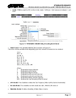
Page 25: ...r of channels to be encoded 1 0 C 2 0 L R 2 0 PS C 2 1 L R S 3 0 L R C 2 2 L R Ls Rs 3 1 L R C S 3 2 L R C Ls Rs 3 2L L R C Ls Rs LFE Where C Represents Centre Channel L Represents Left Channel R Represents Right Channel S Represents Left surround Channel Ls Represents Left surround Channel Rs Represents Right surround Channel LFE Represents Low Frequency Effect Channel LFE Enable This checkbox en...

Page 26: ...scriptor control and type the name of the language 7 5 ENCODER DATA Figure 7 8 9780SLKE2 H264HD Encoding Data Tab View The Encoding Data tab allows access to the following ancillary data Closed Caption Placing a checkmark in the Closed Caption box enables closed captioning WSS Placing a checkmark in the WSS box enables widescreen signalling The user can indicate the line where the WSS signal is pl...

Page 27: ...x0000 packets tells the decoder what programs are in the TS and points to the Program Map Tables PMT which in turn point to the component video audio and data streams that make up the program The PAT period can be specified in this field PMT Period The Program Association Table PAT tells the decoder how many programs there are in the stream and points to the PMTs that contain the information where...

Page 28: ...ication layer in the TCP IP stack and the majority of RTP implementations are built on UDP Network Interface This selector enables the user to select the network interface The options are Data Main Data Backup and Control Destination IP This field enables the user to enter the destination IP address which can be either unicast or multicast Port This field enables the user to enter the port for the...

Page 29: ...P Placing a checkmark in this box enables the use of DHCP on the selected system IP This field enables the user to view or change the IP address of the selected interface Mask This field enables the user to view or change the mask of the selected interface Gateway This field enables the user to set the gateway for the selected interface Encoder Active at Boot Placing a checkmark in this box will e...

Page 30: ...ade Current Version This field displays the current version of firmware Upgrade Unit The user can upgrade the firmware on the unit using this field Click on the Browse button Once the file dialog box appears navigate to the desired firmware file and select it Upgrade The Upgrade button enables the user to upload the selected firmware file Press the Upgrade button to send the new firmware to the un...

Reviews: