HDSD9545DLY - PRO Profanity Bypass Delay Manual
INSTALLATION
Revision
1.3.7
Page 2-5
CAUTION - To reduce the risk of electric shock, grounding of the center pin
of the mains plug must be maintained
2.4.
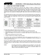
CONNECTING THE VIDEO
2.4.1. Video
Inputs
The program video source should be connected to the
INPUT A
BNC. The HDSD9545DLY-PRO supports
standard definition and high definition digital video in the formats shown in Table 2-3. The video standard
must be set manually to match the incoming video type using the V
ideo Standard
menu item in the
VIDEO
Common
Name
Pixels /
Active Lines
Frame Rate
Progressive
/Interlace
SMPTE
Standard
Valid Genlock
Types
525i/59.94
720 x 486
29.97 (30/1.001)
I
SMPTE
125M
NTSC
625i/50
720 x 576
25
I
EBU TECH
3267-E
PAL
1080i/59.94
1920 x 1080
29.97 (30/1.001)
I
274M
1080i/59.94
NTSC
1080i/50
1920 x 1080
25
I
274M
1080i/50
PAL
720p/59.94
1280 x 720
59.94 (60/1.001)
P
296M
1080i/59.94
720p/59.94
Table 2-3: Video Input Formats
2.4.2. Video
Outputs
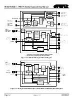
The video output from the five serial digital video outputs is configured at the factory to meet the most
common use of the HDSD9545DLY-PRO, however these outputs can be configured using the
OUTPUT
CONFIG
MENU items. In addition to the default signals provided at the outputs, both the delayed and
non-delayed inputs to the HDSD9545DLY-PRO are also available.
The
OUTPUT A
BNCs normally contain the ‘on-air’ program video output and are normally connected to
the main broadcast chain of your plant. The leftmost
OUTPUT A
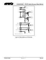
BNC output is protected by a bypass
relay that is activated on power loss, from the front panel or from a GPI. When the relay is active, the left
OUTPUT A
BNC is directly connected to the
INPUT
A
BNC.
The default signal for
OUTPUT B
is the Delayed Program video.
The default signal for
OUTPUT C
is the
Delayed Safe video.
The default signal for
OUTPUT D
and
OUTPUT E
is the quad split output showing
the two video inputs and their delayed feeds.
Summary of Contents for HDSD9545DLY-PRO
Page 2: ......

