HDSD9545DLY - PRO Profanity Bypass Delay Manual
Page 2-8
Revision 1.3.7
INSTALLATION
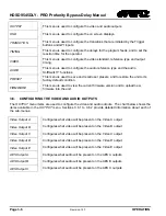
LN/ACT
This dual purpose Green LED indicates that the HDSD9545DLY-PRO has
established a valid linkage to its hub, and whether the HDSD9545DLY-PRO is
sending or receiving data. This LED will be ON when the HDSD9545DLY-PRO has
established a good link to its supporting hub. This gives you a good indication that
the segment is wired correctly. The LED will BLINK when the HDSD9545DLY-PRO
is sending or receiving data. The LED will be OFF if there is no valid connection.
2.7.
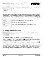
CONNECTING THE GENERAL PURPOSE INPUTS AND OUTPUTS
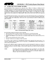
The 25 pin GPI/O connector has 8 programmable general purpose inputs (GPI) and 4 programmable
general purpose outputs (GPO) as shown in Table 2-2. The schematic representation is in Figure 2-2.
The GPIs are opto-isolated inputs that can be powered from an external source or from the frame. The
GPOs are relay contacts that are normally closed when the power to the HDSD9545DLY-PRO is off.
2.7.1. Connecting the General Purpose Inputs
The GPI’s are used as additional triggers to initiate a transition, such as a video and/or audio switch. They
can be programmed using the
TRANSITION
menu.
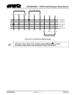
The GPI inputs are active low, which means a ground level on the input will trigger the GPI function when
the Opto isolator is normally powered. See Figure 2-2 and Figure 2-3
The user can connect GP+5V supplied from the frame (Vint pin) into the Vext pin to provide power to the
GPIO opto-isolator circuitry. In this configuration the user can activate GPIs simply by connecting the GPI
input pins to Ground (see Figure 2-3). This can be done with a button, switch, relay or an open collector
transistor.
Warning: Do not connect GP+5V from one unit to another unit’s GP+5V.
Summary of Contents for HDSD9545DLY-PRO
Page 2: ......

