X0400 Series Router Manual
INSTALLATION
Revision 1.4.4
Page - 1
2.
INSTALLATION
2.1.
REAR PANEL
Figure 2-1: X-0401-3G-AES4 Rear Panel Layout with Ethernet Option
Figure 2-2: X0401H-AES4 Rear Panel Layout
Figure 2-3: X0401H-AES4 Rear Panel Layout with Ethernet Option
Figure 2-4: X0401S-AES4 Rear Panel Layout
Figure 2-5: X0401S-AES4 Rear Panel Layout with Ethernet Option
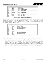
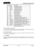
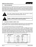
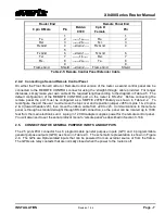
Sections 2.1.1 to 2.1.9 describe the purpose of the rear panel connectors and the specific signals that
should be connected to the routers. Section 7 provides pictorial representations of the video and audio
output configurations for each version of the router.
2.1.1. Standard Definition Digital Video Connections (X0401S)
VIDEO INPUTS 1 to 4:
These BNC connectors are for connecting 10-bit serial digital video signals,
compatible with the SMPTE 259M standard to the respective video input buss.
VIDEO 1:
There are two video output connectors for the Video 1 router buss on X0401S routers. The
Video from the selected Video Input buss will be available on two outputs for the buss.
Summary of Contents for X0400 Series
Page 2: ...This page left intentionally blank ...
Page 6: ...X0400 Series Router Manual Revision 1 4 4 REVISION HISTORY This page left intentionally blank ...
Page 14: ...X0400 Series Router Manual Revision 1 4 4 OVERVIEW This page left intentionally blank ...
Page 42: ...X0400 Series Router Manual Revision 1 4 4 OPERATION This page left intentionally blank ...
Page 90: ...X0400 Series Router Manual Revision 1 4 4 SERIAL CONTROL This page left intentionally blank ...


