X0400 Series Router Manual
Page - 2
Revision 1.4.4
INSTALLATION
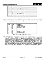
When the bypass relay option is fitted,
INPUT 1
is protected by a bypass relay to the adjacent
VIDEO 1 OUTPUT
BNC. The bypass relays will activate in the event of power loss to the
router and can also be activated from the front panel menu.
2.1.2. High Definition Digital Video Connections (X0401H)
VIDEO INPUTS 1 to 4:
These BNC connectors are for connecting 10-bit serial digital video signals,
compatible with the SMPTE 292M standard to the respective video input buss.
VIDEO 1:
There are two video output connectors for the Video 1 router buss on X0401H. The Video from
the selected Video Input buss will be available on two outputs for the buss.
When the bypass relay option is fitted,
INPUT 1
is protected by a bypass relay to the adjacent
VIDEO 1 OUTPUT
BNC. The bypass relays will activate in the event of power loss to the
router and can also be activated from the front panel menu.
To be able to pass SD, DVB-ASI or 310M through an HD SoftSwitch router, ensure that
the soft switch (i.e. line synchronizer) is off.
2.1.3. 3G Digital Video Connections (X-0401-3G)
VIDEO INPUTS 1 to 4:
These BNC connectors are for connecting 10-bit serial digital video signals,
compatible with the SMPTE 424M standard to the respective video input buss.
VIDEO 1:
There are two video output connectors for the Video 1 router buss on X0401-3G. The Video
from the selected Video Input buss will be available on two outputs for the buss.
When the bypass relay option is fitted,
INPUT 1
is protected by a bypass relay to the adjacent
VIDEO 1 OUTPUT
BNC. The bypass relays will activate in the event of power loss to the
router and can also be activated from the front panel menu.
To be able to pass SD, DVB-ASI or 310M through an 3G SoftSwitch router, ensure that
the soft switch (i.e. line synchronizer) is off.
2.1.4. Digital Video Connections (X0401S-ATSC)
VIDEO INPUTS 1 to 4:
These BNC connectors are for connecting serial digital video signals, compatible
with the SMPTE 310M or SMPTE 259M standard to the respective video input buss. The
reclocker mode must be set to the video standard in use using the
Setup V1 Output
menu item.
VIDEO 1:
There are two video output connectors for the Video 1 router buss on X0401S-ATSC routers.
The Video from the selected Video Input buss will be available on two outputs for the buss.
When the bypass relay option is fitted,
INPUT 1
is protected by a bypass relay to the adjacent
VIDEO 1 OUTPUT
BNC. The bypass relays will activate in the event of power loss to the
router and can also be activated from the front panel menu.
Summary of Contents for X0400 Series
Page 2: ...This page left intentionally blank ...
Page 6: ...X0400 Series Router Manual Revision 1 4 4 REVISION HISTORY This page left intentionally blank ...
Page 14: ...X0400 Series Router Manual Revision 1 4 4 OVERVIEW This page left intentionally blank ...
Page 42: ...X0400 Series Router Manual Revision 1 4 4 OPERATION This page left intentionally blank ...
Page 90: ...X0400 Series Router Manual Revision 1 4 4 SERIAL CONTROL This page left intentionally blank ...

