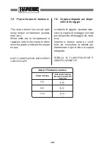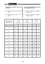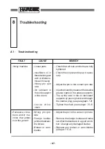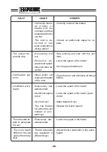
- 80 -
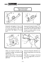
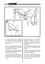
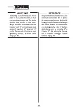
IMPORTANTE
Il tagliente della lama deve essere
orientato concorde con il senso
di rotazione del rotore. I bulloni di
fissaggio delle lame con la flangia
del rotore devono essere montati
con la testa della vite “1” dal lato
della lama, con la rondella “2” e
il dado “3” dal lato della flangia.
Per il corretto serraggio vedere
tabella a pag. 85.
IMPORTANT
The sharp side of the blades must
point in the same direction as that
in which the rotor turns. The bolts
that fix the blades to the rotor
flange must be mounted with the
head of bolt “1” on the blade side
and with washer “2” and nut “3”
on the flange side. For the correct
tightening torque, see the table
on page 85.
Summary of Contents for HARDEE HT3
Page 2: ......
Page 22: ...10...
Page 27: ...15 39914100 g 2 2 1 g 2 2 2 Z11 399143000 g 2 2 4 Z13 Z14 g 2 2 3 399CEE001 399CEE002 Z12...
Page 42: ...30 g 2 9 1 Z06...
Page 43: ...31 1 g 2 9 2 399CEE001 39914100 Z11 Z12...
Page 44: ...32 g 2 9 3 2 72 0386 00...
Page 45: ...33 3 g 2 9 4 72 0390 00...
Page 46: ...34 5 g 2 9 5 72 0391 00...
Page 50: ...38...
Page 98: ...86...
Page 106: ...94...
Page 107: ...95 9 Assembly instructions for Kit standing jack Schema di montaggio per Piedino di appoggio...
Page 108: ...STANDING JACK PIEDISTAL STUTZHALTER PIEDINO DI APPOGGIO HT2 1 10 12 11 4 5...
Page 110: ...7 3 6 2 4 5 STANDING JACK PIEDISTAL STUTZHALTER PIEDINO DI APPOGGIO HT3...
Page 112: ...7 12 12 8 10 9 11 6 STANDING JACK PIEDISTAL STUTZHALTER PIEDINO DI APPOGGIO HT4...
Page 114: ...STANDING JACK PIEDISTAL STUTZHALTER PIEDINO DI APPOGGIO HT6 7 11 11 8 10 9 12 6...
Page 116: ...STANDING JACK PIEDISTAL STUTZHALTER PIEDINO DI APPOGGIO HT9 8 13 13 9 11 10 12 7...
Page 118: ......
Page 119: ......


